Home > Product > DCS control system > TU810V1 3BSE013230R1 base module
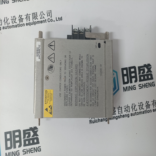
TU810V1 3BSE013230R1 base module
- Product ID: TU810V1 3BSE013230R1
- Brand: ABB
- Place of origin: The Swiss
- Goods status: new/used
- Delivery date: stock
- The quality assurance period: 365 days
- Phone/WhatsApp/WeChat:+86 15270269218
- Email:stodcdcs@gmail.com
- Tags:TU810V13BSE013230R1base module
- Get the latest price:Click to consult
TU810V1 3BSE013230R1 base module
Follow these guidelines when you select 2-slot addressing:
• Place an 8-point output module opposite a 16-point input module.
• An I/O group having a 16-point input and output module cannot have a corresponding I/O group in the complementary chassis.
• You can place an output module opposite another output module; they reflect the same bits in the output image table.
When you select 2-slot addressing, each pair of slots (one I/O group) is assigned to the corresponding pair of words in the input and output image tables. You assign one I/O rack number to eight I/O groups
You can use block-transfer modules in a complementary I/O system
with these restrictions:
• When using double-slot block-transfer modules:
• The left slot of the complementary I/O group must be empty.
• You can only place an 8-point output module (if any) in the right slot of the complementary I/O group.
• When using single-slot block-transfer modules:
• The right slot of the primary I/O group can be another single-slot block-transfer module, or an 8-point input or output module.
• The left slot of the complementary I/O group must be empty.
• You can place an 8-point output module in the right slot of the complementary I/O group; this slot must be empty if the corresponding slot in the primary I/O group is a single-slot block-transfer module.
The processor addresses one I/O module
slot as one I/O group. Concept: The physical address of each I/O group corresponds to an input and output image table word. The type of module you install (8, 16, or 32-point) determines the number of bits in these words that are used. You select 1-slot addressing by setting switches 5 and 6 of the I/O chassis backplane switch assembly: • switch 5 to the ON position • switch 6 to the OFF position With 1-slot addressing, because 16 input AND 16 output bits are available in the processor’s image table for each I/O slot, you can use any mix of 8 or 16-point I/O modules in the I/O chassis.