Home > Product > Servo control system > KONGSBERG RDC2 Driver module
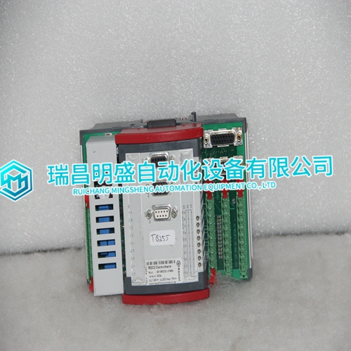
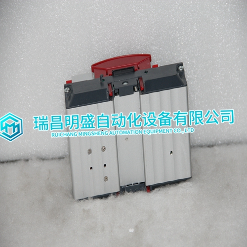
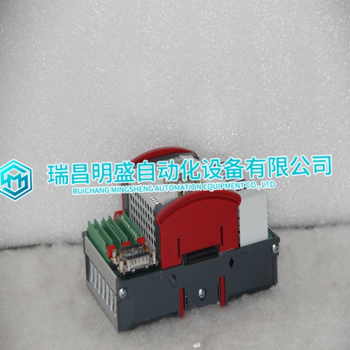
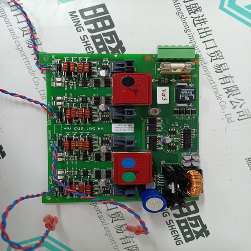
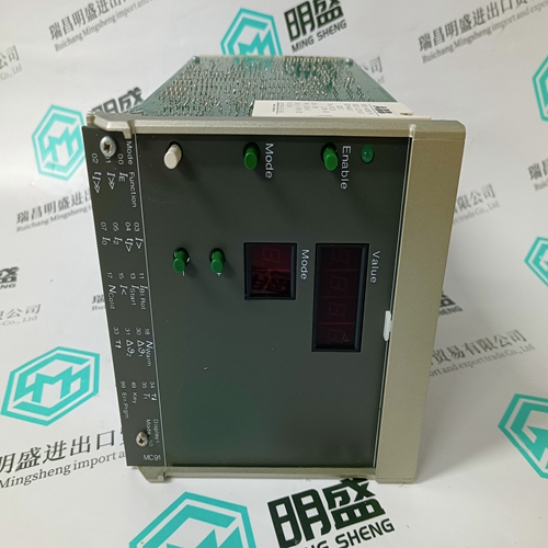
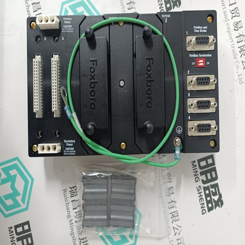
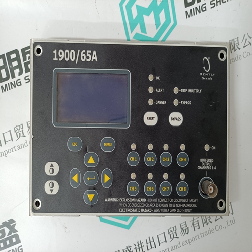
KONGSBERG RDC2 Driver module
- Product ID: RDC2
- Brand: KONGSBERG
- Place of origin: The United States
- Goods status: new/used
- Delivery date: stock
- The quality assurance period: 365 days
- Phone/WhatsApp/WeChat:+86 15270269218
- Email:stodcdcs@gmail.com
- Tags:KONGSBERGRDC2Driver module
- Get the latest price:Click to consult
KONGSBERG RDC2 Driver module
To install ProSoft Configuration Builder from the Product CD
1 Insert the ProSoft Solutions Product CD into the CD drive of your PC. Wait for the startup screen to appear.
2 On the startup screen, click PRODUCT DOCUMENTATION. This action opens an explorer window.
3 Click to open the UTILITIES folder. This folder contains all of the applications and files you will need to set up and configure your module.
4 Double-click the SETUPCONFIGURATIONTOOL folder, double-click the "PCB_*.EXE" file and follow the instructions on your screen to install the software on your PC.
The information represented by the "*" character in the file name is the PCB version number and, therefore, subject to change as new versions of PCB are released. Note: Many of the configuration and maintenance procedures use files and other utilities on the CD-ROM. You may wish to copy the files from the Utilities folder on the CD-ROM to a convenient location on your hard drive.
Setting Jumpers
The Setup Jumper acts as "write protection" for the module’s flash memory. In "write protected" mode, the Setup pins are not connected, and the module’s firmware cannot be overwritten. Do not jumper the Setup pins together unless you are directed to do so by ProSoft Technical Support. The following illustration shows the MVI46-MNET jumper configuration. Note: If you are installing the module in a remote rack, you may prefer to leave the Setup pins jumpered. That way, you can update the module’s firmware without requiring physical access to the module.
Install the Module in the Rack
If you have not already installed and configured your SLC processor and power supply, please do so before installing the MVI46-MNET module. Refer to your Rockwell Automation product documentation for installation instructions. Warning: You must follow all safety instructions when installing this or any other electronic devices. Failure to follow safety procedures could result in damage to hardware or data, or even serious injury or death to personnel. Refer to the documentation for each device you plan to connect to verify that suitable safety procedures are in place before installing or servicing the device. After you have checked the placement of the jumpers, insert MVI46-MNET into the SLC™ chassis. Use the same technique recommended by Rockwell Automation to remove and install SLC™ modules.
