Home > Product > PLC programmable module > VME162PA344SE Serial communication Card
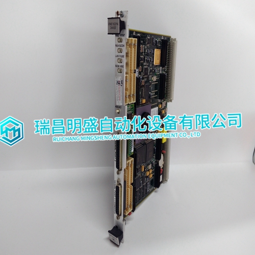
VME162PA344SE Serial communication Card
- Product ID: VME162PA344SE
- Brand: MOTOROLA
- Place of origin: The United States
- Goods status: new/used
- Delivery date: stock
- The quality assurance period: 365 days
- Phone/WhatsApp/WeChat:+86 15270269218
- Email:stodcdcs@gmail.com
- Tags:VME162PA344SESerial communication Card
- Get the latest price:Click to consult
VME162PA344SE Serial communication Card
1 Turn power OFF.
2 Align the module with the top and bottom guides, and slide it into the rack until the module is firmly against the backplane connector.
3 With a firm but steady push, snap the module into place.
4 Check that the holding clips on the top and bottom of the module are securely in the locking holes of the rack.
5 Make a note of the slot location. You will need to identify the slot in which the module is installed in order for the sample program to work correctly. Slot numbers are identified on the green circuit board (backplane) of the SLC rack.
6 Turn power ON. Note: If you insert the module improperly, the system may stop working, or may behave unpredictably
Connect your PC to the Module
With the module securely mounted, connect your PC to the Configuration/Debug port using an RJ45-DB-9 Serial Adapter Cable and a Null Modem Cable. 1 Attach both cables as shown. 2 Insert the RJ45 cable connector into the Configuration/Debug port of the module. 3 Attach the other end to the serial port on your PC.
ProSoft Configuration Builder
ProSoft Configuration Builder (PCB) provides a quick and easy way to manage module configuration files customized to meet your application needs. PCB is not only a powerful solution for new configuration files, but also allows you to import information from previously installed (known working) configurations to new projects.If you have used other Windows configuration tools before, you will find the screen layout familiar. PCB’s window consists of a tree view on the left, and an information pane and a configuration pane on the right side of the window. When you first start PCB, the tree view consists of folders for DEFAULT PROJECT and DEFAULT LOCATION, with a DEFAULT MODULE in the Default Location folder. The following illustration shows the PCB window with a new project.