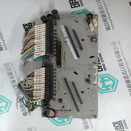
Home > Product > DCS control system > 3ADT313900R1501 SDCS-CON-4 Dc control card
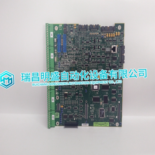
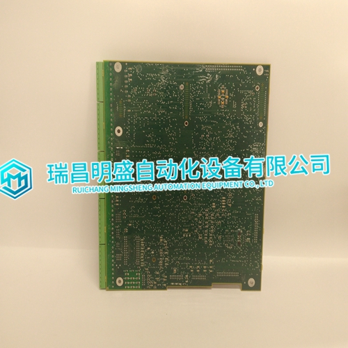
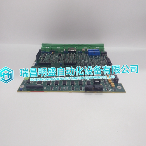
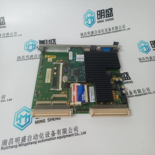
3ADT313900R1501 SDCS-CON-4 Dc control card
- Product ID: 3ADT313900R1501 SDCS-CON-4
- Brand: ABB
- Place of origin: The Swiss
- Goods status: new/used
- Delivery date: stock
- The quality assurance period: 365 days
- Phone/WhatsApp/WeChat:+86 15270269218
- Email:xiamen2018@foxmail.com
- Tags:3ADT313900R1501SDCS-CON-4Dc control card
- Get the latest price:Click to consult
3ADT313900R1501 SDCS-CON-4 Dc control card
This parameter defines if the data received from the Server is to be ordered differently than received from the Server device. This parameter is helpful when dealing with floating-point or other multi-register values, as there is no standard method of storage of these data types in Server devices. This parameter can be set to order the register data received in an order useful by other applications.Use a value of 502 when addressing Modbus TCP/IP servers that are compatible with the Schneider Electric MBAP specifications (this will be most devices). If a server implementation supports another service port, enter the value here.Most Modbus devices only accept an address in the range of 1 to 247, so be careful. If the value is set to zero, the command will be a broadcast message on the network. The Modbus protocol permits broadcast commands for write operations. Do not use this node address for read operations.
Modbus Function
This parameter specifies the Modbus function to be executed by the command. These function codes are defined in the Modbus protocol. The following table defines the purpose of each function supported by the module. More information on the protocol is available from the Schneider Electric web site
This section contains database offset information used by the servers when accessed by external clients. These offsets can be utilized to segment the database by data type.
MB Address in Device
This parameter specifies the starting Modbus register or digital point address to be considered by the command in the Modbus slave device. Refer to the documentation of each Modbus slave device on the network for their register and digital point address assignments. The FC determines the addresses range and that this value will be the register or bit OFFSET into a given data range. For instance, if the command is to be a bit command (FC 1, 2, 5, or 15) to Read/Write a Coil 0X address 00001, then the value to enter here would be 0. For Coil address 00110, the value here would be 109. For register Read/Write commands (FC 3, 4, 6, or 16) in the 3X (FC4) or 4X (FC3), say 30001 or 40001, the value here would, again be 0. For 31101 or 41101, the value to enter for this parameter would be 1100.
