Home > Product > Gas turbine system > VMIPCI-5565-110000 Steam gas turbine module
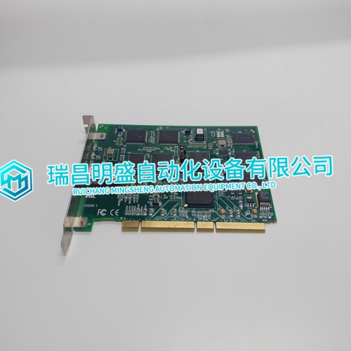
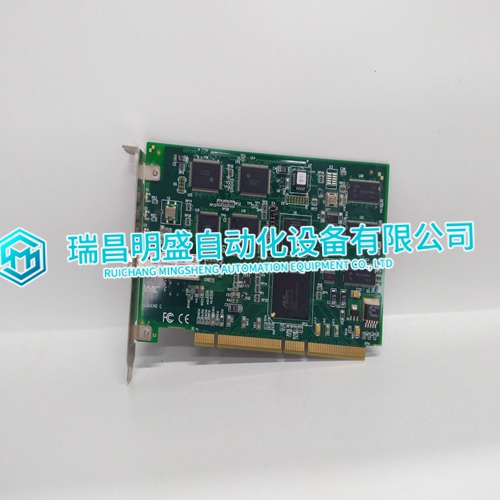
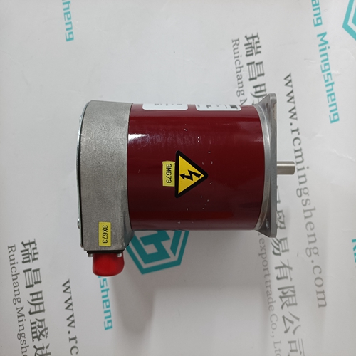
VMIPCI-5565-110000 Steam gas turbine module
- Product ID: VMIPCI-5565-110000
- Brand: GE
- Place of origin: The United States
- Goods status: new/used
- Delivery date: stock
- The quality assurance period: 365 days
- Phone/WhatsApp/WeChat:+86 15270269218
- Email:stodcdcs@gmail.com
- Tags:VMIPCI-5565-110000Steam gas turbine module
- Get the latest price:Click to consult
VMIPCI-5565-110000 Steam gas turbine module
All data transferred between the module and the processor over the backplane is through the M1 file. Ladder logic must be written in the SLC processor to interface the M1 file data in the module's internal database. All data used by the module is stored in its internal database. This database is defined as a virtual Modbus data table with addresses from 0 (40001 Modbus) to 4999 (45000 Modbus). The following illustration shows the layout of the database: Module’s Internal Database Structure
Data registers in the module above 4999
are used for command control. When special values are written in this register set, the module will perform specific functions. The following topics define the special functions handled by the module. Initialize Output Data When the module performs a restart operation, it will request output data from the processor to initialize the module’s output data. Use the Initialize Output Data parameter (page 24) in the configuration to bring the module to a known state after a restart operation. The following table describes the structure of the request block.
Command Control Blocks
Command control blocks are special blocks used to control the module. The current version of the software supports four command control blocks: event command control, command control, warm boot and cold boot. Register 5000 of the module's M1 file is used for this feature. The following table lists the command control block numbers recognized by the module. The command control value of 1000 is placed in register 5000 of the M1 file to indicate that the module is requesting initialization of the M1 data file. Ladder logic in the processor must recognize this command and place the correct information in the M1file. After the data transfer is complete, the ladder logic should place a value of 1001 in register 5000 of the module’s M1 file. The following table describes the structure of the response block.
