Home > Product > DCS control system > 3BHE020356R0101 GF D233A controller
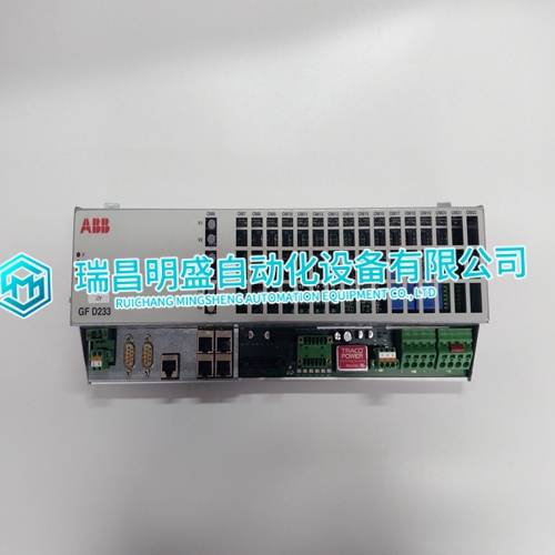
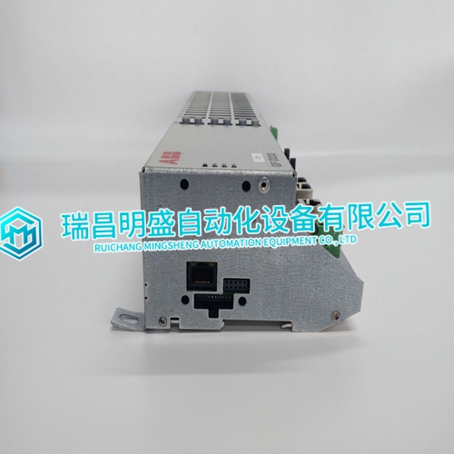
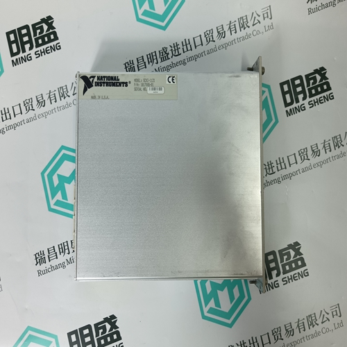
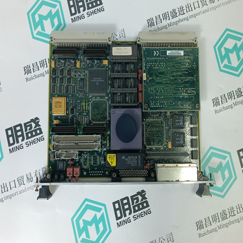
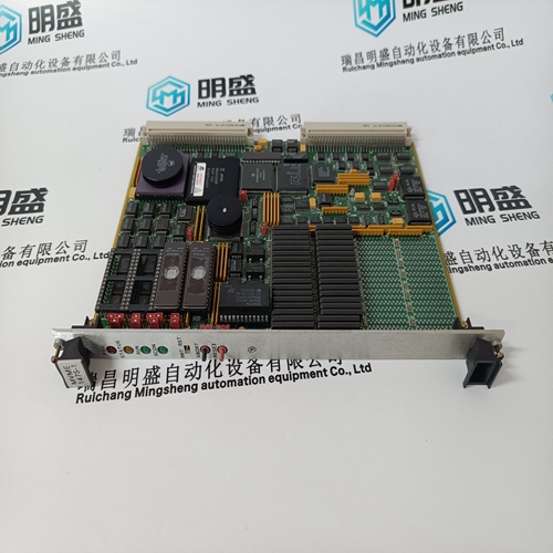
3BHE020356R0101 GF D233A controller
- Product ID: 3BHE020356R0101 GF D233A
- Brand: ABB
- Place of origin: The Swiss
- Goods status: new/used
- Delivery date: stock
- The quality assurance period: 365 days
- Phone/WhatsApp/WeChat:+86 15270269218
- Email:xiamen2018@foxmail.com
- Tags:3BHE020356R0101GF D233Acontroller
- Get the latest price:Click to consult
3BHE020356R0101 GF D233A controller
Command control blocks place commands from the command list into the command queue. The client has a command list of up to 100 commands. The module services commands in the queue before the user defined command list. This gives high priority to commands in the queue. Commands placed in the queue through this mechanism must be defined in the module's command list. Under normal command list execution, the module will only execute commands with the Enable parameter set to one or two. If the value is set to zero, the command is skipped. Commands may be placed in the command queue with an Enable parameter set to zero using this feature. These commands can then be executed using the command control blocks. One to six commands can be placed in the command queue with a single request. The following table describes the format for this block.
The last digit in the block code defines
the number of commands to process in the block. For example, a block code of 5003 contains 3 command indexes that are to be placed in the command queue. The Command index parameters in the block have a range of 0 to 99 and correspond to the module's command list entries. The module responds to a command control block with a block containing the number of commands added to the command queue for the port. The following table describes the format for this block.
The Server Driver allows the MVI46-MNET module to respond to data read and write commands issued by clients on the Modbus TCP/IP network. The following flow chart and associated table describe the flow of data into and out of the module.
This block is sent from the SLC
processor to the module when the module is required to perform a warm-boot (software reset) operation. This block is commonly sent to the module any time configuration data modifications are made in the controller tags data area. This will force the module to read the new configuration information and to restart. The following table describes the format of the control block.This block is sent from the SLC processor to the module when the module is required to perform the cold boot (hardware reset) operation. This block is sent to the module when a hardware problem is detected by the ladder logic that requires a hardware reset. The following table describes the format of the control block.