Home > Product > DCS control system > R-S108V01-16-24VDC-C10-1 structure module
R-S108V01-16-24VDC-C10-1 structure module
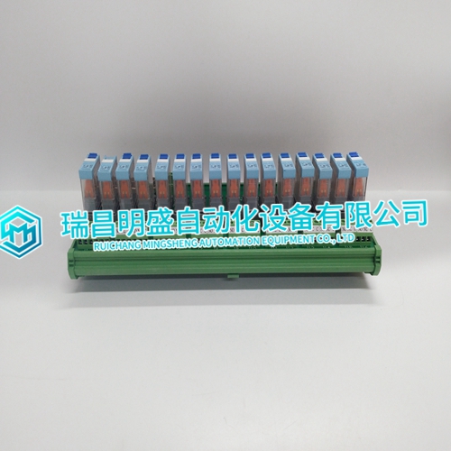
- Product ID: R-S108V01-16-24VDC-C10-1
- Brand: ABB
- Place of origin: The Swiss
- Goods status: new/used
- Delivery date: stock
- The quality assurance period: 365 days
- Phone/WhatsApp/WeChat:+86 15270269218
- Email:stodcdcs@gmail.com
- Tags:R-S108V01-16-24VDC-C10-1structure module
- Get the latest price:Click to consult
R-S108V01-16-24VDC-C10-1 structure module
An example response to Read Input Status is as shown in Figure C4. The data is packed one bit for each input. The response includes the Slave address, function code, quantity of data characters, the data characters, and error checking. Data will be packed with one bit for each input (1=ON, 0=OFF). The lower order bit of the first character contains the addressed input, and the remainder follow. For input quantities that are not even multiples of eight, the last characters will be filled in with zeros at high order end. The quantity of data characters is always specified as a quantity of RTU characters, that is, the number is the same whether RTU or ASCII is used. Because the Slave interface device is serviced at the end of a controller's scan, data will reflect input status at the end of the scan. Some Slaves will limit the quantity of inputs provided each scan; thus, for large coil quantities, multiple PC transactions must be made using coil status for sequential scans
Read Holding Registers
Read Holding Registers (03) allows the user to obtain the binary contents of holding registers 4xxxx in the addressed Slave. The registers can store the numerical values of associated timers and counters which can be driven to external devices. The addressing allows up to 125 registers to obtained at each request; however, the specific Slave device may have restriction that lower this maximum quantity. The registers are numbered form zero (40001 = zero, 40002 = one, and so on). The broadcast mode is not allowed.
Response
The addressed Slave responds with its address and the function code, followed by the information field. The information field contains 1 byte describing the quantity of data bytes to be returned. The contents of the registers requested (DATA) are two bytes each, with the binary content right justified within each pair of characters. The first byte includes the high order bits and the second, the low order bits. Because the Slave interface device is normally serviced at the end of the controller's scan, the data will reflect the register content at the end of the scan. Some Slaves will limit the quantity of register content provided each scan; thus for large register quantities, multiple transmissions will be made using register content from sequential scans.