Home > Product > DCS control system > E69F-B12-S converter module
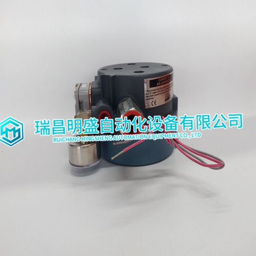
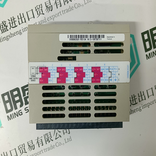
E69F-B12-S converter module
- Product ID: E69F-B12-S
- Brand: FOXBORO
- Place of origin: The United States
- Goods status: new/used
- Delivery date: stock
- The quality assurance period: 365 days
- Phone/WhatsApp/WeChat:+86 15270269218
- Email:stodcdcs@gmail.com
- Tags:E69F-B12-Sconverter module
- Get the latest price:Click to consult
E69F-B12-S converter module
To Achieve Better EMC Protection
• Initially, use the original cabling from the supplier primarily.
• Use shielded cables for RS232 communication.
• Use twisted pair and shielded cabling for RS422 and RS485.
• Use the cabling intended for the bus type; Ethernet, Profibus, CC-Link, CAN, Device Net etc.
• Install and connect according to applicable specifications for the relevant bus standard.
• Use shielded cabling for Ethernet, preferably with foil + braided shield.
• D-sub covers should be shielded, and the shield should be connected to the cover 360 ° where the cable comes in.
• Connect the shield at both ends.
With longer distances
there is a risk that the ground potential may be different. In that case, the shield should only be connected at one end. A good alternative is to connect the other end of the shield to the ground via a 0.1 uF/250 V plastic capacitor. Both ends are then connected to the ground in terms of HF, but only connected to the ground at one end in terms of LF, thus avoiding the 50 Hz grounding loops.
• Use an EMC cable gland or regular plastic cable gland, remove the outer jacket and connect the shield to the installation plate with a 360 ° metal cable clamp
• Place the 24 V DC and communications cabling in one cable trunk/cable duct and 230/380 V AC in another. If the cables need to be crossed, cross them at 90 ° only. Avoid combining the cabling for stronger 24 V DC outputs with the communication cabling.
• Ferrite cores that are snapped onto the shielded cabling may remove minor disturbances. Large ferrite pieces that are snapped onto unshielded cabling and where the wires go 2-4 times around the cores are approximately 5-25 times more efficient.
Ambient Temperature
The maximum ambient temperature for the operator panel is provided in the specifications. The ambient temperature refers to the temperature in the device cabinet which cools the panel’s electronics.In most cases, the ambient temperature for the operator panel is significantly higher than the device cabinet’s ambient temperature. If the cabinet is tall and there are a number of heat-generating devices, the temperature at the top of the cabinet will be considerably higher than the theoretical temperature increase that would be expected. All electronics are sensitive to heat. The lifespan of an electrolytic capacitor is cut in half with an 8-10 °C increase in temperature. A 15-20 °C temperature increase results in a quarter of the lifespan etc. Rittal has a good program for estimating the anticipated average temperature in the cabinet as well as a large program for controlling the temperature in the device cabinet.