Home > Product > DCS control system > NF93A-2 HESG440280R2 module
NF93A-2 HESG440280R2 module
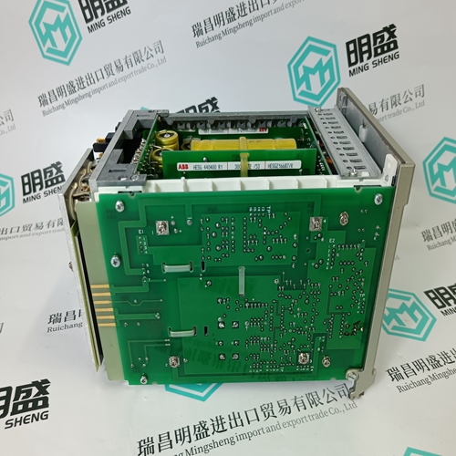
- Product ID: NF93A-2 HESG440280R2
- Brand: ABB
- Place of origin: The Swiss
- Goods status: new/used
- Delivery date: stock
- The quality assurance period: 365 days
- Phone/WhatsApp/WeChat:+86 15270269218
- Email:stodcdcs@gmail.com
- Tags:NF93A-2 HESG440280R2module
- Get the latest price:Click to consult
The main products
Spare parts spare parts, the DCS control system of PLC system and the robot system spare parts,
Brand advantage: Allen Bradley, BentlyNevada, ABB, Emerson Ovation, Honeywell DCS, Rockwell ICS Triplex, FOXBORO, Schneider PLC, GE Fanuc, Motorola, HIMA, TRICONEX, Prosoft etc. Various kinds of imported industrial parts
NF93A-2 HESG440280R2 module
Removal and replacement of cover ï Remove all detachable (screw-type) terminal plugs from the RDCU, and disconnect any cables connected to the unit. Remove any optional modules. If desired, the unit can be removed from the mounting rail as described above to facilitate the following steps. ï With a screwdriver or similar tool, carefully release the four cover retaining clips (C) on the right-hand side while simultaneously pulling the right-hand edge of the cover gently away from the base plate. ï Shift the cover to the left to free its left-hand edge, then pull it to detach it completely from the base and circuit board. ï Replace the cover in reverse order to the above (left-hand edge first). If the unit is already mounted onto its mounting rail, align the retaining clips (A) so that they catch on the mounting rail.General The shields of the I/O cables should be grounded to the chassis of the cubicle as close to the RDCU as possible. Use grommets at all cable entries. Handle fibre optic cables with care. When unplugging fibre optic cables, always grab the connector, not the cable itself. Do not touch the ends of the fibres with bare hands as the fibre is extremely sensitive to dirt. The maximum long-term tensile load for the fibre optic cables included is 1 N; the minimum short-term bend radius is 25 mm (1î). Digital/Analogue input/output connections See the Firmware Manual of the application program in question.
Installation of optional modules
Follow the instructions given in the user manual of the module. Other connections See also the wiring diagram below. Powering the RDCU The RDCU is powered through connector X34. The unit can be powered from the power supply board of the inverter (or IGBT supply) module, provided that the maximum current of 1 A is not exceeded. The RDCU can also be powered from an external 24 V DC supply. Note also that the current consumption of the RDCU is dependent on the optional modules attached. (For current consumption of optional modules, see their respective user manuals.) Fibre optic connection to inverter/IGBT supply module Connect the PPCS link of the AINT (ACS 800 series modules) or NINT (ACS 600 series modules) board of the inverter (or IGBT supply) module to fibre optic connectors V57 and V68 of the RDCU. Note: The recommended maximum distances for the fibre optic link is 10 m (for plastic [POF] cable). In case longer distances are required, contact an ABB representative.