Home > Product > Gas turbine system > PQMII-T20 General electric (ge)
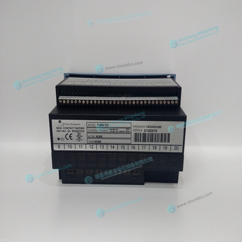
PQMII-T20 General electric (ge)
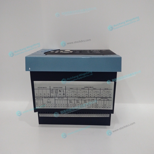
- Product ID: PQMII-T20
- Brand: GE
- Place of origin: The United States
- Goods status: new/used
- Delivery date: stock
- The quality assurance period: 365 days
- Phone/WhatsApp/WeChat:+86 15270269218
- Email:xiamen2018@foxmail.com
- Tags:PQMII-T20General electric (ge)
- Get the latest price:Click to consult
PQMII-T20 General electric (ge)
Stepper Motor with Step and Direction Signals The DMC-21x2/21x3 can control stepper motors. In this mode, the controller provides two signals to connect to the stepper motor amplifier: Step and Direction. For stepper motor operation, the controller does not require an encoder and operates the stepper motor in an open loop fashion. Chapter 2 describes the proper connection and procedure for using stepper motors.
The main processing unit of the DMC-21x2/21x3 is a specialized 32-Bit Motorola 68331 Series Microcomputer with 4 Meg RAM and 4 Meg Flash EEPROM. The RAM provides memory for variables, array elements and application programs. The flash EEPROM provides non-volatile storage of variables, programs, and arrays. It also contains the DMC-21x2/21x3 firmware.
Overview of Amplifiers
The amplifiers should be suitable for the motor and may be linear or pulse-width-modulated. An amplifier may have current feedback, voltage feedback or velocity feedback. Amplifiers in Current Mode Amplifiers in current mode should accept an analog command signal in the +/-10 Volt range. The amplifier gain should be set such that a +10V command will generate the maximum required current. For example, if the motor peak current is 10A, the amplifier gain should be 1 A/V. Amplifiers in Velocity Mode For velocity mode amplifiers, a command signal of 10 Volts should run the motor at the maximum required speed. The velocity gain should be set such that an input signal of 10V runs the motor at the maximum required speed. Stepper Motor Amplifiers For step motors, the amplifiers should accept step and direction signals.
Motor Interface
Galil’s GL-1800 custom, sub-micron gate array performs quadrature decoding of each encoder at up to 12 MHz. For standard servo operation, the controller generates a +/-10 Volt analog signal (16 Bit DAC). For sinusoidal commutation operation, the controller uses 2 DACs to generate 2 +/-10Volt analog signals. For stepper motor operation, the controller generates a step and direction signal. Communication The communication interface with the DMC-21x2/21x3 consists of a RS-232 port and 10 BaseT Ethernet port. The RS-232 channel can generate up to 19.2Kbaud. General I/O The DMC-21x2/21x3 provides interface circuitry for 8 TTL inputs, 8 TTL outputs. The DMC-21x2 also has an additional 40 I/O daughterboard that can be ordered as an option. Unused auxiliary encoder inputs may also be used as additional inputs (2 inputs / each axis). The general inputs can also be used as high speed latches for each axis. A high speed encoder compare output is also provided. The DMC-2152 through DMC-2182 controller provides an additional 8 TTL inputs and 8 TTL outputs.