Home > Product > DCS control system > SNAT604 5761861-2B Sequence control module
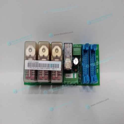
SNAT604 5761861-2B Sequence control module
- Product ID: SNAT604 5761861-2B
- Brand: ABB
- Place of origin: The Swiss
- Goods status: new/used
- Delivery date: stock
- The quality assurance period: 365 days
- Phone/WhatsApp/WeChat:+86 15270269218
- Email:stodcdcs@gmail.com
- Tags:SNAT6045761861-2BSequence control module
- Get the latest price:Click to consult
SNAT604 5761861-2B Sequence control module
A motor converts current into torque which produces motion. Each axis of motion requires a motor sized properly to move the load at the required speed and acceleration. The Galil "Motion Component Selector" software can help with motor sizing. Contact Galil at 800-377-6329 if you would like this product. The motor may be a step or servo motor and can be brush-type or brushless, rotary or linear. For step motors, the controller can be configured to control full-step, half-step, or microstep drives. An encoder is not required when step motors are used.
The standard voltage level is TTL (zero to five volts), however, voltage levels up to 12 Volts are acceptable. (If using differential signals, 12 Volts can be input directly to the DMC-21x2/21x3. Single-ended 12 Volt signals require a bias voltage input to the complementary inputs). To interface with other types of position sensors such as resolvers or absolute encoders, Galil can customize the controller and command set. Please contact Galil and talk to one of our applications engineers about your particular system requirements.
Amplifier (Driver)
For each axis, the power amplifier converts a +/-10 Volt signal from the controller into current to drive the motor. For stepper motors, the amplifier converts step and direction signals into current. The amplifier should be sized properly to meet the power requirements of the motor. For brushless motors, an amplifier that provides electronic commutation is required or the controller must be configured to provide sinusoidal commutation. The amplifiers may be either pulse-width-modulated (PWM) or linear. They may also be configured for operation with or without a tachometer. For current amplifiers, the amplifier gain should be set such that a 10 Volt command generates the maximum required current. For example, if the motor peak current is 10A, the amplifier gain should be 1 A/V. For velocity mode amplifiers, 10 Volts should run the motor at the maximum speed.
Encoder
An encoder translates motion into electrical pulses which are fed back into the controller. The DMC21x2/21x3 accepts feedback from either a rotary or linear encoder. Typical encoders provide two channels in quadrature, known as CHA and CHB. This type of encoder is known as a quadrature encoder. Quadrature encoders may be either single-ended (CHA and CHB) or differential (CHA,CHAand CHB,CHB-). The DMC-21x2/21x3 decodes either type into quadrature states or four times the number of cycles. Encoders may also have a third channel (or index) for synchronization. For stepper motors, the DMC-21x2/21x3 can also interface to encoders with pulse and direction signals. There is no limit on encoder line density, however, the input frequency to the controller must not exceed 3,000,000 full encoder cycles/second (12,000,000 quadrature counts/sec). For example, if the encoder line density is 10000 cycles per inch, the maximum speed is 300 inches/second. If higher encoder frequency is required, please consult the factory.