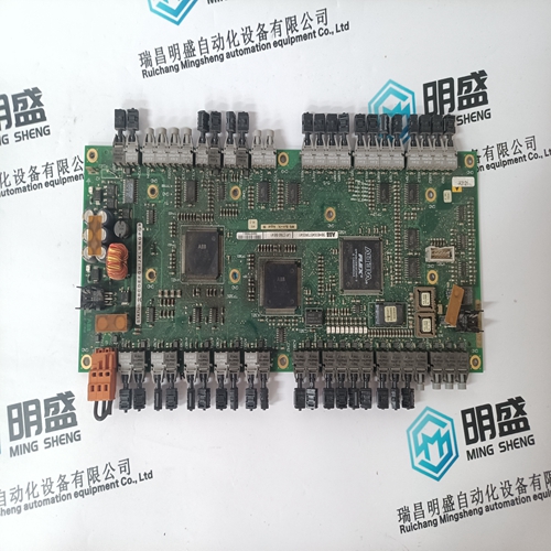
Home > Product > DCS control system > 5SHX1445H0001 3BHL00391P0101 Thyristor module
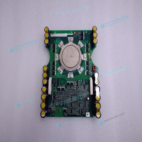
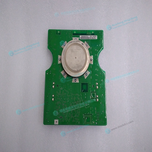
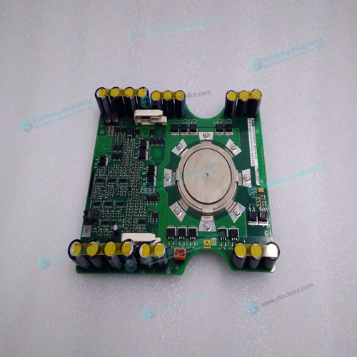
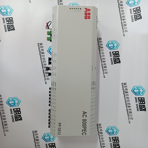
5SHX1445H0001 3BHL00391P0101 Thyristor module
- Product ID: 5SHX1445H0001 3BHL00391P0101
- Brand: ABB
- Place of origin: The Swiss
- Goods status: new/used
- Delivery date: stock
- The quality assurance period: 365 days
- Phone/WhatsApp/WeChat:+86 15270269218
- Email:xiamen2018@foxmail.com
- Tags:5SHX1445H00013BHL00391P0101Thyristor module
- Get the latest price:Click to consult
5SHX1445H0001 3BHL00391P0101 Thyristor module
The BA command also reconfigures the controller to indicate that the controller has one less axis of 'standard' control for each axis of sinusoidal commutation. For example, if the command BAA is given to a DMC-2142 controller, the controller will be re-configured to a DMC-2132 controller. By definition, a DMC-2132 controls 3 axes: A,B and C. The 'D' axis is no longer available since the output DAC is being used for sinusoidal commutation. Further instruction for sinusoidal commutation connections are discussed in Step 6. Stepper Motor Operation To configure the DMC-21x2 for stepper motor operation, the controller requires a jumper for each stepper motor and the command, MT, must be given. The installation of the stepper motor jumper is discussed in the following section entitled "Installing Jumpers on the DMC-21x2". Further instruction for stepper motor connections are discussed in Step 9.
Master Reset and Upgrade Jumpers
JP4 on the main board contains two jumpers, MRST and UPGRD. The MRST jumper is the Master Reset jumper. When MRST is connected, the controller will perform a master reset upon PC power up or upon the reset input going low. Whenever the controller has a master reset, all programs, arrays, variables, and motion control parameters stored in EEPROM will be ERASED. The UPGRD jumper enables the user to unconditionally update the controller’s firmware. This jumper is not necessary for firmware updates when the controller is operating normally, but may be necessary in cases of corrupted EEPROM. EEPROM corruption should never occur. However, it is possible if there is a power fault during a firmware update. If EEPROM corruption occurs, your controller may not operate properly. In this case, install the UPGRD Jumper and use the update firmware function on the Galil Terminal to re-load the system firmware.
Stepper Motor Jumpers
For each axis that will used for stepper motor operation, the corresponding stepper mode (SM) jumper must be connected. The stepper mode jumpers, labeled JP5 and JP7 are located directly beside the GL-1800 IC's on the main board (see the diagram of the DMC-21x2). The individual jumpers are labeled E thru H and configure the controller for ‘Stepper Motors’ for the corresponding axes X-W when installed. Contact the Galil factory if stepper motor jumpers should be placed on your controller with each order for special part numbers.