Home > Product > DCS control system > 3BHE033067R0103 GCC960C103 controller
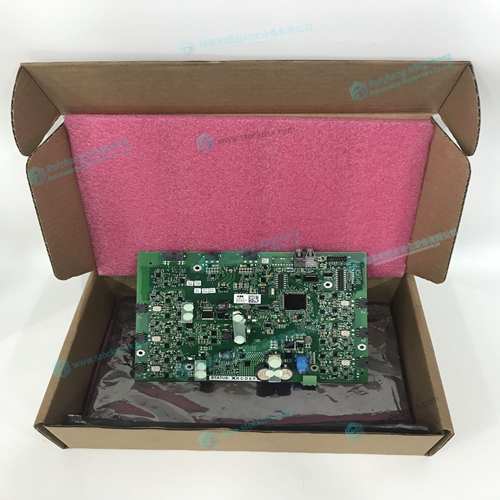
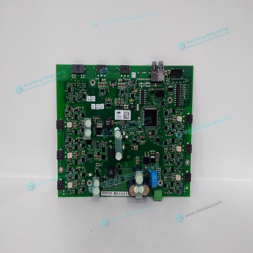
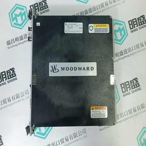
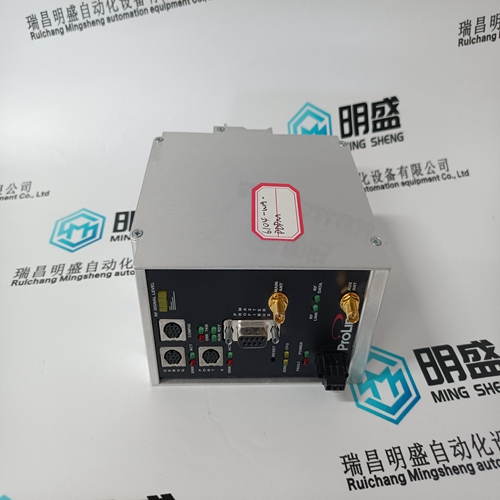
3BHE033067R0103 GCC960C103 controller
- Product ID: 3BHE033067R0103 GCC960C103
- Brand: ABB
- Place of origin: The Swiss
- Goods status: new/used
- Delivery date: stock
- The quality assurance period: 365 days
- Phone/WhatsApp/WeChat:+86 15270269218
- Email:stodcdcs@gmail.com
- Tags:3BHE033067R0103GCC960C103controller
- Get the latest price:Click to consult
3BHE033067R0103 GCC960C103 controller
This command causes the controller to be reconfigured as a DMC-2152 controller. The A and C axes are configured for sinusoidal commutation. The first phase of the A axis will be the motor command A signal. The second phase of the A axis will be F signal. The first phase of the C axis will be the motor command C signal. The second phase of the C axis will be the motor command G signal.Connect the motor to the amplifier with no connection to the controller. Consult the amplifier documentation for instructions regarding proper connections. Connect and turn-on the amplifier power supply. If the amplifiers are operating properly, the motor should stand still even when the amplifiers are powered up.
Make Connections to Amplifier and Encoder
Once you have established communications between the software and the DMC-21x2, you are ready to connect the rest of the motion control system. The motion control system typically consists of a breakout module such as the ICM-2900 Interface Module, an amplifier for each axis of motion, and a motor to transform the current from the amplifier into torque for motion. If you are using an ICM-2900, connect it to the DMC-21x2 via the 100-pin high density cable. The ICM-2900 provides screw terminals for access to the connections described in the following discussion. Motion Controllers with more than 4 axes require a second ICM-2900 and 100-pin cable. System connection procedures will depend on system components and motor types. Any combination of motor types can be used with the DMC-21x2. If sinusoidal commutation is to be used, special attention must be paid to the reconfiguration of axes
Connect the amplifier enable signal
Before making any connections from the amplifier to the controller, you need to verify that the ground level of the amplifier is either floating or at the same potential as earth. WARNING: When the amplifier ground is not isolated from the power line or when it has a different potential than that of the computer ground, serious damage may result to the computer, controller and amplifier. If you are not sure about the potential of the ground levels, connect the two ground signals (amplifier ground and earth) by a 10 KΩ resistor and measure the voltage across the resistor. Only if the voltage is zero, connect the two ground signals directly. The amplifier enable signal is used by the controller to disable the motor. This signal is labeled AMPENA for the A axis on the ICM-2900 and should be connected to the enable signal on the amplifier. Note that many amplifiers designate this signal as the INHIBIT signal. Use the command, MO, to disable the motor amplifiers - check to ensure that the motor amplifiers have been disabled (often this is indicated by an LED on the amplifier).