Home > Product > DCS control system > 3BHE037649R0101 PDD500A101 controller
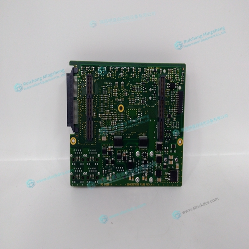
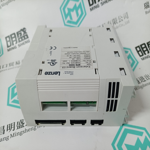
3BHE037649R0101 PDD500A101 controller
- Product ID: 3BHE037649R0101 PDD500A101
- Brand: ABB
- Place of origin: The Swiss
- Goods status: new/used
- Delivery date: stock
- The quality assurance period: 365 days
- Phone/WhatsApp/WeChat:+86 15270269218
- Email:stodcdcs@gmail.com
- Tags:3BHE037649R0101PDD500A101controller
- Get the latest price:Click to consult
3BHE037649R0101 PDD500A101 controller
The standard configuration of the AMPEN signal is TTL active high. In other words, the AMPEN signal will be high when the controller expects the amplifier to be enabled. The polarity and the amplitude can be changed if you are using the ICM-2900 interface board. To change the polarity from active high (5 volts = enable, zero volts = disable) to active low (zero volts = enable, 5 volts = disable), replace the 7407 IC with a 7406. Note that many amplifiers designate the enable input as ‘inhibit’. To change the voltage level of the AMPEN signal, note the state of the resistor pack on the ICM-2900. When Pin 1 is on the 5V mark, the output voltage is 0-5V. To change to 12 volts, pull the resistor pack and rotate it so that Pin 1 is on the 12 volt side. If you remove the resistor pack, the output signal is an open collector, allowing the user to connect an external supply with voltages up to 24V (through a current limiting resistor).
Connect the encoders
For stepper motor operation, an encoder is optional. For servo motor operation, if you have a preferred definition of the forward and reverse directions, make sure that the encoder wiring is consistent with that definition. The DMC-21x2 accepts single-ended or differential encoder feedback with or without an index pulse. If you are not using the ICM-2900 you will need to consult the appendix for the encoder pinouts for connection to the motion controller. The ICM-2900 accepts encoder feedback via individual signal leads. Simply match the leads from the encoder you are using to the encoder feedback inputs on the interconnect board. The signal leads are labeled CHA (channel A), CHB (channel B), and INDEX. For differential encoders, the complement signals are labeled CHA-, CHB-, and INDEX-.
When using pulse and direction encoders
the pulse signal is connected to CHA and the
direction signal is connected to CHB. The controller must be configured for pulse and direction
with the command CE. See the command summary for further information on the command CE.
Step D. Verify proper encoder operation.
Start with the A encoder first. Once it is connected, turn the motor shaft and interrogate the
position with the instruction TPA