Home > Product > DCS control system > 3BHE039203R0101 5SXE12-0184 GVC736CE101 card
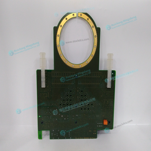
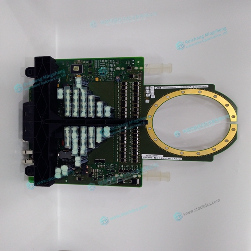
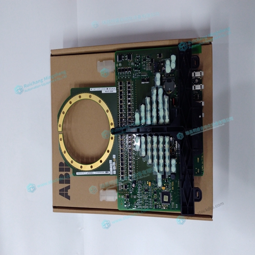
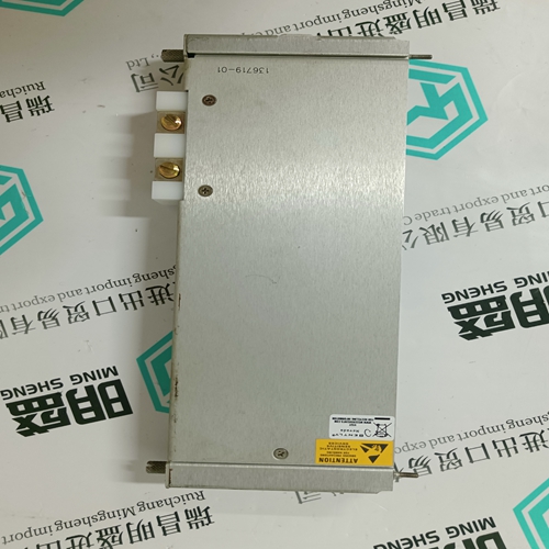
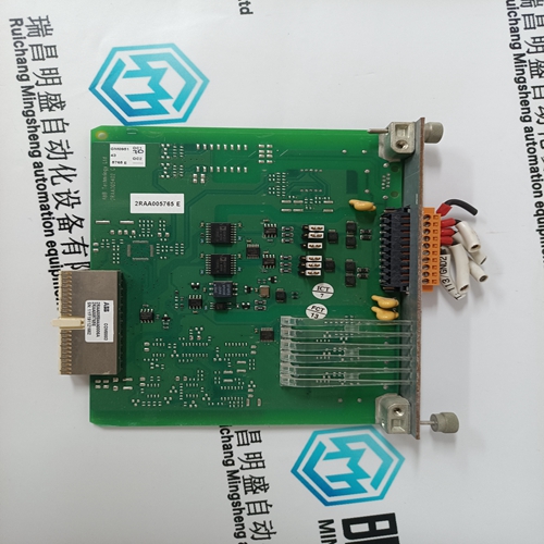
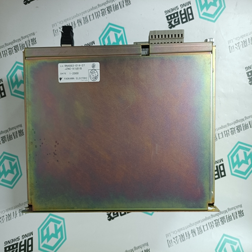
3BHE039203R0101 5SXE12-0184 GVC736CE101 card
- Product ID: 3BHE039203R0101 5SXE12-0184 GVC736CE101
- Brand: ABB
- Place of origin: The Swiss
- Goods status: new/used
- Delivery date: stock
- The quality assurance period: 365 days
- Phone/WhatsApp/WeChat:+86 15270269218
- Email:stodcdcs@gmail.com
- Tags:3BHE039203R01015SXE12-0184GVC736CE101card
- Get the latest price:Click to consult
3BHE039203R0101 5SXE12-0184 GVC736CE101 card
Connect Hall Sensors if available.
Hall sensors are only used with sinusoidal commutation and are not necessary for proper
operation. The use of hall sensors allows the controller to automatically estimate the
commutation phase upon reset and also provides the controller the ability to set a more precise
commutation phase. Without hall sensors, the commutation phase must be determined
manually.
The hall effect sensors are connected to the digital inputs of the controller. These inputs can
be used with the general use inputs (bits 1-8), the auxiliary encoder inputs (bits 81-96), or the
extended I/O inputs of the DMC-21x2 controller (bits 17-56).
NOTE: The general use inputs are TTL - for more information regarding the digital inputs, see
Chapter 3, Connecting Hardware.
Connect Standard Servo Motors
The following discussion applies to connecting the DMC-21x2 controller to standard servo motor amplifiers: The motor and the amplifier may be configured in the torque or the velocity mode. In the torque mode, the amplifier gain should be such that a 10 Volt signal generates the maximum required current. In the velocity mode, a command signal of 10 Volts should run the motor at the maximum required speed. Step by step directions on servo system setup are also included on the WSDK (Windows Servo Design Kit) software offered by Galil. See section on WSDK for more details.
Check the Polarity of the Feedback Loop
It is assumed that the motor and amplifier are connected together and that the encoder is
operating correctly (Step B). Before connecting the motor amplifiers to the controller, read
the following discussion on setting Error Limits and Torque Limits. Note that this discussion
only uses the A axis as an example.
Step B. Set the Error Limit as a Safety Precaution
Usually, there is uncertainty about the correct polarity of the feedback. The wrong polarity
causes the motor to run away from the starting position. Using a terminal program, such as
Galil SmartTerminal, the following parameters can be given to avoid system damage:
Input the commands:
ER 2000