Home > Product > DCS control system > 3BHE042816R0101 PCD244A101 controller card
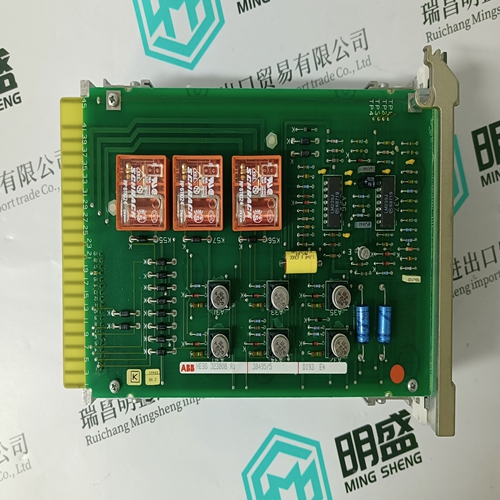
3BHE042816R0101 PCD244A101 controller card
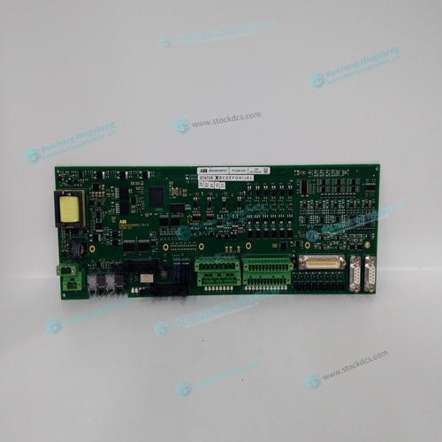
- Product ID: 3BHE042816R0101 PCD244A101
- Brand: ABB
- Place of origin: The Swiss
- Goods status: new/used
- Delivery date: stock
- The quality assurance period: 365 days
- Phone/WhatsApp/WeChat:+86 15270269218
- Email:stodcdcs@gmail.com
- Tags:3BHE042816R0101PCD244A101controller card
- Get the latest price:Click to consult
3BHE042816R0101 PCD244A101 controller card
To limit the maximum voltage signal to your amplifier, the DMC-21x2 controller has a torque
limit command, TL. This command sets the maximum voltage output of the controller and
can be used to avoid excessive torque or speed when initially setting up a servo system.
When operating an amplifier in torque mode, the voltage output of the controller will be
directly related to the torque output of the motor. The user is responsible for determining this
relationship using the documentation of the motor and amplifier. The torque limit can be set
to a value that will limit the motors output torque.
When operating an amplifier in velocity or voltage mode, the voltage output of the controller
will be directly related to the velocity of the motor. The user is responsible for determining
this relationship using the documentation of the motor and amplifier. The torque limit can be
set to a value that will limit the speed of the motor.Once the correct polarity of the feedback loop has been determined, the torque limit
should, in general, be increased to the default value of 9.998. The servo will not operate properly
if the torque limit is below the normal operating range. See description of TL in the command
reference.
Connect the Motor
Once the parameters have been set, connect the analog motor command signal (ACMD) to the
amplifier input.
To test the polarity of the feedback, command a move with the instruction:
PR 1000