Home > Product > Robot control system > VIBRO C002292.01 9100131600 VB-430 module
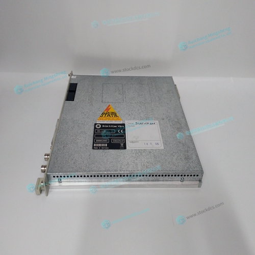
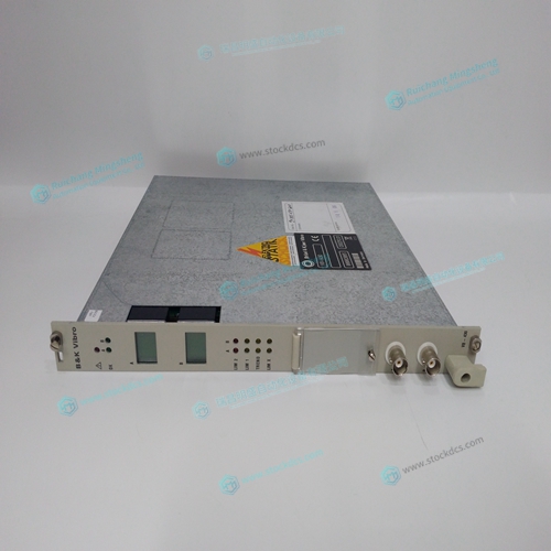
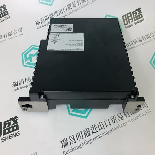
VIBRO C002292.01 9100131600 VB-430 module
- Product ID: C002292.01 9100131600 VB-430
- Brand: VIBRO
- Place of origin: The United States
- Goods status: new/used
- Delivery date: stock
- The quality assurance period: 365 days
- Phone/WhatsApp/WeChat:+86 15270269218
- Email:stodcdcs@gmail.com
- Tags:VIBROC002292.01 9100131600 VB-430module
- Get the latest price:Click to consult
VIBRO C002292.01 9100131600 VB-430 module
Use the command, BC. This command uses the hall transitions to determine the commutation phase. Ideally, the hall sensor transitions will be separated by exactly 60° and any deviation from 60° will affect the accuracy of this method. If the hall sensors are accurate, this method is recommended. The BC command monitors the hall sensors during a move and monitors the Hall sensors for a transition point. When that occurs, the controller computes the commutation phase and sets it. For example, to initialize the A axis motor upon power or reset, the following commands may be given: SHA ;Enable A axis motor
Connect Step Motors
In Stepper Motor operation, the pulse output signal has a 50% duty cycle. Step motors operate open loop and do not require encoder feedback. When a stepper is used, the auxiliary encoder for the corresponding axis is unavailable for an external connection. If an encoder is used for position feedback, connect the encoder to the main encoder input corresponding to that axis. The commanded position of the stepper can be interrogated with RP or TD. The encoder position can be interrogated with TP. The frequency of the step motor pulses can be smoothed with the filter parameter, KS. The KS parameter has a range between 0.5 and 8, where 8 implies the largest amount of smoothing. See Command Reference regarding KS. The DMC-21x2 profiler commands the step motor amplifier. All DMC-21x2 motion commands apply such as PR, PA, VP, CR and JG. The acceleration, deceleration, slew speed and smoothing are also used. Since step motors run open-loop, the PID filter does not function and the position error is not generated.
To connect step motors with the DMC-21x2
you must follow this procedure: Step A. Install SM jumpers Each axis of the DMC-21x2 that will operate a stepper motor must have the corresponding stepper motor jumper installed. Step B. Connect step and direction signals from controller to motor amplifier From the controller to respective signals on your step motor amplifier. (These signals are labeled PULSX and DIRX for the A-axis on the ICM-2900). Consult the documentation for your step motor amplifier. Step C. Configure DMC-21x2 for motor type using MT command. You can configure the DMC21x2 for active high or active low pulses. Use the command MT 2 for active low step motor pulses and MT -2 for active high step motor pulses. See description of the MT command in the Command Reference.