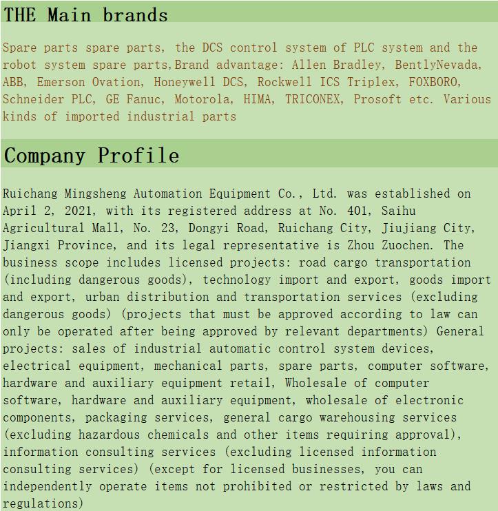
Home > Product > DCS control system > YOKOGAWA 16407-01-1 Industrial card
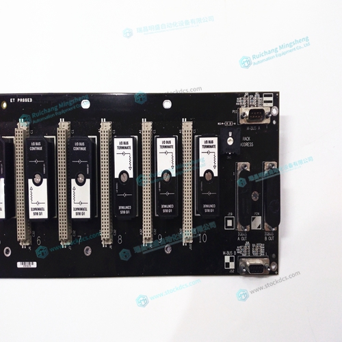
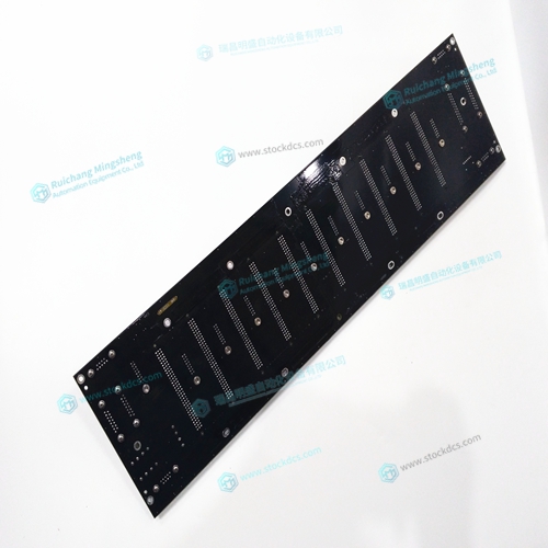
YOKOGAWA 16407-01-1 Industrial card
- Product ID: 16407-01-1
- Brand: YOKOGAWA
- Place of origin: JAPAN
- Goods status: new/used
- Delivery date: stock
- The quality assurance period: 365 days
- Phone/WhatsApp/WeChat:+86 15270269218
- Email:xiamen2018@foxmail.com
- Tags:YOKOGAWA16407-01-1Industrial card
- Get the latest price:Click to consult
YOKOGAWA 16407-01-1 Industrial card
Set Torque Limit as a Safety Precaution
To limit the maximum voltage signal to your amplifier, the DMC-21x3 controller has a torque
limit command, TL. This command sets the maximum voltage output of the controller and
can be used to avoid excessive torque or speed when initially setting up a servo system.
When operating an amplifier in torque mode, the voltage output of the controller will be
directly related to the torque output of the motor. The user is responsible for determining this
relationship using the documentation of the motor and amplifier. The torque limit can be set
to a value that will limit the motors output torque.
When operating an amplifier in velocity or voltage mode, the voltage output of the controller
will be directly related to the velocity of the motor. The user is responsible for determining
this relationship using the documentation of the motor and amplifier. The torque limit can be
set to a value that will limit the speed of the motor.
Connect the Motor
Once the parameters have been set, connect the analog motor command signal (ACMD) to the
amplifier input.
To test the polarity of the feedback, command a move with the instruction:
PR 1000
Inverting the Loop Polarity
When the polarity of the feedback is incorrect, the user must invert the loop polarity and this may be accomplished by several methods. If you are driving a brush-type DC motor, the simplest way is to invert the two motor wires (typically red and black). For example, switch the M1 and M2 connections going from your amplifier to the motor. When driving a brushless motor, the polarity reversal may be done with the encoder. If you are using a single-ended encoder, interchange the signal CHA and CHB. If, on the other hand, you are using a differential encoder, interchange only CHA+ and CHA-. The loop polarity and encoder polarity can also be affected through software with the MT, and CE commands. For more details on the MT command or the CE command, see the Command Reference section.