Home > Product > DCS control system > YOKOGAWA 8596020000 Communication module
YOKOGAWA 8596020000 Communication module
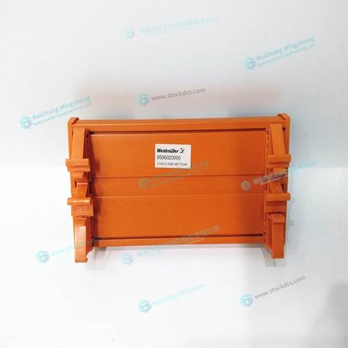
- Product ID: 8596020000
- Brand: YOKOGAWA
- Place of origin: JAPAN
- Goods status: new/used
- Delivery date: stock
- The quality assurance period: 365 days
- Phone/WhatsApp/WeChat:+86 15270269218
- Email:stodcdcs@gmail.com
- Tags:YOKOGAWA8596020000Communication module
- Get the latest price:Click to consult
YOKOGAWA 8596020000 Communication module
This command causes the controller to be reconfigured as a DMC-2153 controller. The A and C axes are configured for sinusoidal commutation. The first phase of the A axis will be the motor command A signal. The second phase of the A axis will be the motor command F signal. The first phase of the C axis will be the motor command C signal. The second phase of the C axis will be the motor command G signal. Step C. Specify the Size of the Magnetic Cycle. Use the command, BM, to specify the size of the brushless motors magnetic cycle in encoder counts. For example, if the X axis is a linear motor where the magnetic cycle length is 62 mm, and the encoder resolution is 1 micron, the cycle equals 62,000 counts. This can be commanded with the command.
Use the brushless motor setup command
BS, to test the polarity of the output DACs. This command applies a certain voltage, V, to each phase for some time T, and checks to see if the motion is in the correct direction. The user must specify the value for V and T. For example, the command BSA = 2,700 will test the A axis with a voltage of 2 volts, applying it for 700 milliseconds for each phase. In response, this test indicates whether the DAC wiring is correct and will indicate an approximate value of BM. If the wiring is correct, the approximate value for BM will agree with the value used in the previous step. NOTE: In order to properly conduct the brushless setup, the motor must be allowed to move a minimum of one magnetic cycle in both directions.
When using Galil Windows software
the timeout must be set to a minimum of 10 seconds (time-out = 10000) when executing the BS command. This allows the software to retrieve all messages returned from the controller. Step D - part 2 (Systems with Hall Sensors Only). Test the Hall Sensor Configuration. Since the Hall sensors are connected randomly, it is very likely that they are wired in the incorrect order. The brushless setup command indicates the correct wiring of the Hall sensors. The hall sensor wires should be re-configured to reflect the results of this test. The setup command also reports the position offset of the hall transition point and the zero phase of the motor commutation. The zero transition of the Hall sensors typically occur at 0°, 30° or 90° of the phase commutation. It is necessary to inform the controller about the offset of the Hall sensor and this is done with the instruction, BB.