Home > Product > DCS control system > PSCAMAAN 16404-5003 Communication module
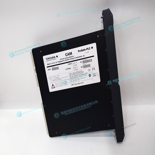
PSCAMAAN 16404-5003 Communication module
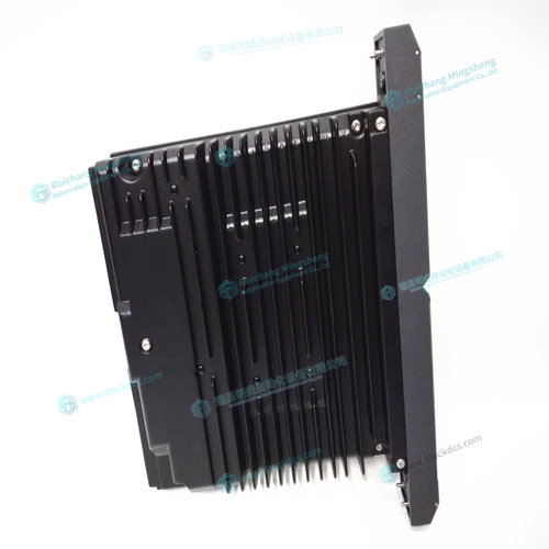
- Product ID: PSCAMAAN 16404-5003
- Brand: YOKOGAWA
- Place of origin: JAPAN
- Goods status: new/used
- Delivery date: stock
- The quality assurance period: 365 days
- Phone/WhatsApp/WeChat:+86 15270269218
- Email:stodcdcs@gmail.com
- Tags:PSCAMAAN 16404-5003Communication module
- Get the latest price:Click to consult
PSCAMAAN 16404-5003 Communication module
Adjusting the tuning parameters required when using servo motors (standard or sinusoidal commutation). The system compensation provides fast and accurate response and the following presentation suggests a simple and easy way for compensation. More advanced design methods are available with software design tools from Galil, such as the Windows Servo Design Kit (WSDK software ) The filter has three parameters: the damping, KD; the proportional gain, KP; and the integrator, KI. The parameters should be selected in this order.For more damping, you can increase KD (maximum is 4095). Increase gradually and stop after the motor vibrates. A vibration is noticed by audible sound or by interrogation. If you send the command a few times, and get varying responses, especially with reversing polarity, it indicates system vibration. When this happens, simply reduce KD. Next you need to increase the value of KP gradually (maximum allowed is 1023). You can monitor the improvement in the response with the Tell Error instruction
As the proportional gain is increased, the error decreases
Again, the system may vibrate if the gain is too high. In this case, reduce KP. Typically, KP should
not be greater than KD/4. (When the amplifier is configured in the current mode).
Finally, to select KI, start with zero value and increase it gradually. The integrator eliminates the
position error, resulting in improved accuracy. Therefore, the response to the instruction
TEA