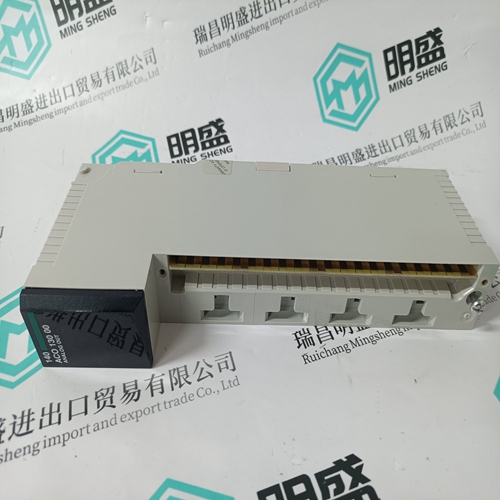
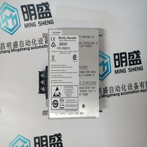
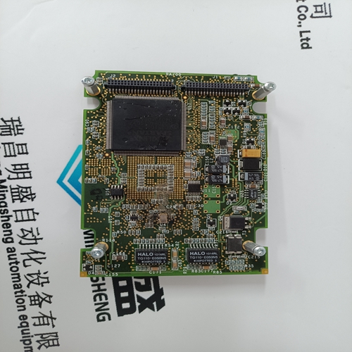
Home > Product > DCS control system > PSCDM024DCBAN 16800-5415 mechanical module
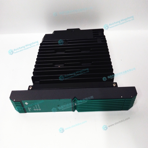
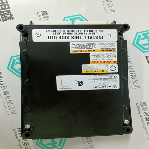
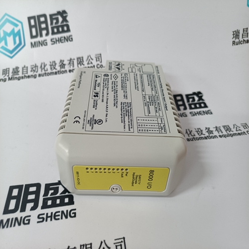
PSCDM024DCBAN 16800-5415 mechanical module
- Product ID: PSCDM024DCBAN 16800-5415
- Brand: YOKOGAWA
- Place of origin: JAPAN
- Goods status: new/used
- Delivery date: stock
- The quality assurance period: 365 days
- Phone/WhatsApp/WeChat:+86 15270269218
- Email:stodcdcs@gmail.com
- Tags:PSCDM024DCBAN 16800-5415mechanical module
- Get the latest price:Click to consult
PSCDM024DCBAN 16800-5415 mechanical module
Amplifier Interface The DMC-21x2/21x3 command voltage ranges between +/-10V. This signal, along with GND, provides the input to the motor amplifiers. The amplifiers must be sized appropriately to drive the motors and existing load. For best performance, the amplifiers should be configured for a torque (current) mode of operation with no additional compensation. The gain should be set such that a 10 Volt input results in the maximum required current. The DMC-21x2/21x3 also provides an amplifier enable signal, AMPEN. This signal changes under the following conditions: the motor-off command, MO, is given, the watchdog timer activates, or the OE1command (Enable Off On Error) is given and the position error exceeds the error limit. As shown in Figure 3-1, AMPEN can be used to disable the amplifier for these conditions. The standard configuration of the AMPEN signal is TTL active high. In other words, the AMPEN signal will be high when the controller expects the amplifier to be enabled.
The polarity and the amplitude
can be changed if you are using the ICM-2900 interface board (21x2) or the ICM-20100/ ICM-20105 (DMC-21x3). To change the polarity from active high (5 volts= enable, zero volts = disable) to active low (zero volts = enable, 5 volts= disable), replace the 7407 IC with a 7406. Note that many amplifiers designate the enable input as ‘inhibit’.To change the voltage level of the AMPEN signal on the ICM-2900, note the state of the resistor pack on the ICM-2900. When Pin 1 is on the 5V mark, the output voltage is 0-5V. To change to 12 volts, pull the resistor pack and rotate it so that Pin 1 is on the 12 volt side. If you remove the resistor pack, the output signal is an open collector, allowing the user to connect an external supply with voltages up to 24V. To change the voltage level of the AMPEN signal on the ICM-20105, please refer to the DMC-21x3 Accessories Manual.
The Auxiliary Encoder Inputs
The auxiliary encoder inputs can be used for general use. For each axis, the controller has one auxiliary encoder and each auxiliary encoder consists of two inputs, channel A and channel B. The auxiliary encoder inputs are mapped to the inputs 81-96. Each input from the auxiliary encoder is a differential line receiver and can accept voltage levels between +/- 12Volts. The inputs have been configured to accept TTL level signals. To connect TTL signals, simply connect the signal to the + input and leave the - input disconnected. For other signal levels, the - input should be connected to a voltage that is ½ of the full voltage range (for example, connect the - input to 6 volts if the signal is a 0 - 12 volt logic).


Temporal Ming sheng automation equipment co., LTD., specialized in (DCS system) (robotic system) (large) servo control system (PLC system) module for spare parts sales, inventory adequate, product quality, let you have no trouble back at home of our main products are widely used in metallurgy, petroleum, glass, aluminum manufacturing, petrochemical industry, coal mine, papermaking, printing, textile printing and dyeing, machinery, electronics, automobile manufacturing, tobacco, plastics machinery, electric power, water conservancy, water treatment/environmental protection, municipal engineering, boiler heating, energy, power transmission and distribution and so on
Brand advantage
GE gas turbine electric, ABB, Bently bentley, Emerson Emerson, Honeywell Honeywell, ICS Triplex, WOODWARD WOODWARD, FOXBORO FOXBORO, SST, HIMA hermas, Motorola Motorola, TRICONEX invensys, SCHNEIDER SCHNEIDER A - B, Prosoft import module in Europe and America and so on
