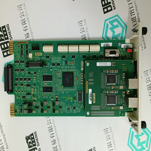
Home > Product > Gas turbine system > HE693ADC409A-22 industrial module
HE693ADC409A-22 industrial module
- Product ID: HE693ADC409A-22
- Brand: GE
- Place of origin: the United States
- Goods status: new/used
- Delivery date: stock
- The quality assurance period: 365 days
- Phone/WhatsApp/WeChat:+86 15270269218
- Email:stodcdcs@gmail.com
- Tags:HE693ADC409A-22industrial module
- Get the latest price:Click to consult
The main products
Spare parts spare parts, the DCS control system of PLC system and the robot system spare parts,
Brand advantage: Allen Bradley, BentlyNevada, ABB, Emerson Ovation, Honeywell DCS, Rockwell ICS Triplex, FOXBORO, Schneider PLC, GE Fanuc, Motorola, HIMA, TRICONEX, Prosoft etc. Various kinds of imported industrial parts
HE693ADC409A-22 industrial module
All shields must be connected to ground at the connector closest to the midpoint of the section. Note: Terminating resistors (300-Ohm) must be placed across pins 6 and 7 of the connectors at the two ends of each bus section. Intermediate drops in the section must not be terminated. Note: All daisy-chain cable connections must be made inside the hood of the connector.Connecting the FIP Bus to the Bus Controller Attach FIP bus cable(s) to the connectors on the front of the Bus Controller. When installed in a single media or simplex configuration, either connector may be used. When installed in a dual media or redundant configuration, both the Channel 1 and 2 connectors must be used. Both connectors accept a standard 9–pin D–type male connector.Note: If only one FIP bus is used, cover the unused FIP bus connector with an anti-static cap. The unused connector must be protected in this manner to meet IEEE specification 801.2. Pin Assignments for the FIP Bus Connectors The diagram below shows pin assignments for both FIP bus connectors on the front of the Bus Controller.
Observing the LEDs
The top LED indicates module health. The bottom 5 LEDs indicate communications activity on the FIP bus. Two LEDs are dedicated to each of the two FIP channels. MODULE OK – Shows the status of the FIP Bus Controller. This LED blinks during power-up diagnostics and should remain on as long as power is applied to the Bus Controller. BUS ARBITER –Shows the operational status of the Bus Arbiter function. CARRIER DETECT – A Carrier Detect LED is ON when the Bus Controller is detecting a carrier signal on the FIP bus attached to that channel. TRANSMIT ENABLE – A Transmit Enable LED is ON when the Bus Controller transmits data on the FIP bus attached to that channel. The intensity of this LED indicates the level of transmission activity in the bus. A dimly-lit Transmit Enable LED indicates low activity; a brightly-lit Transmit Enable LED indicates high activity Use the Restart button to Restart the module or Reload the software and Restart the module. Note that the Restart button does not function during the module’s diagnostic phase (Module OK is blinking) or when the PLC is actually scanning I/O (CPU RUN is ON). To Restart the Module: Press the Restart button for less than 3 seconds.
