Home > Product > DCS control system > TK457V050 3BSE004394R1 cable
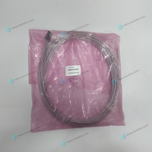
TK457V050 3BSE004394R1 cable
- Product ID: TK457V050 3BSE004394R1
- Brand: ABB
- Place of origin: The Swiss
- Goods status: new/used
- Delivery date: stock
- The quality assurance period: 365 days
- Phone/WhatsApp/WeChat:+86 15270269218
- Email:stodcdcs@gmail.com
- Tags:TK457V0503BSE004394R1cable
- Get the latest price:Click to consult
TK457V050 3BSE004394R1 cable
An A-B-C system must cut the pattern shown in Fig. 7.2. The A-B table moves the plate while the Caxis raises and lowers the cutting tool. The solid curves in Fig. 7.2 indicate sections where cutting takes place. Those must be performed at a feedrate of 1 inch per second. The dashed line corresponds to non-cutting moves and should be performed at 5 inch per second. The acceleration rate is 0.1 g. The motion starts at point A, with the C-axis raised. An A-B motion to point B is followed by lowering the C-axis and performing a cut along the circle. Once the circular motion is completed, the C-axis is raised and the motion continues to point C, etc. Assume that all of the 3 axes are driven by lead screws with 10 turns-per-inch pitch.
Backlash Compensation by Sampled Dual-Loop
The continuous dual loop, enabled by the DV1 function is an effective way to compensate for backlash. In some cases, however, when the backlash magnitude is large, it may be difficult to stabilize the system. In those cases, it may be easier to use the sampled dual loop method described below. This design example addresses the basic problems of backlash in motion control systems. The objective is to control the position of a linear slide precisely. The slide is to be controlled by a rotary motor, which is coupled to the slide by a leadscrew. Such a leadscrew has a backlash of 4 micron, and the required position accuracy is for 0.5 micron. The basic dilemma is where to mount the sensor. If you use a rotary sensor, you get a 4 micron backlash error. On the other hand, if you use a linear encoder, the backlash in the feedback loop will cause oscillations due to instability.
An alternative approach is the dual-loop
where we use two sensors, rotary and linear. The rotary sensor assures stability (because the position loop is closed before the backlash) whereas the linear sensor provides accurate load position information. The operation principle is to drive the motor to a given rotary position near the final point. Once there, the load position is read to find the position error and the controller commands the motor to move to a new rotary position which eliminates the position error. Since the required accuracy is 0.5 micron, the resolution of the linear sensor should preferably be twice finer. A linear sensor with a resolution of 0.25 micron allows a position error of +/-2 counts. The dual-loop approach requires the resolution of the rotary sensor to be equal or better than that of the linear system. Assuming that the pitch of the lead screw is 2.5mm (approximately 10 turns per inch), a rotary encoder of 2500 lines per turn or 10,000 count per revolution results in a rotary resolution of 0.25 micron. This results in equal resolution on both linear and rotary sensors.


1.Payment method and delivery
Shipment: EMS,DHL,UPS & FEDEX
Payment: T/T or Western Union
2. About us
We are professional company and we are expert in this business, we have highly experienced production team, or sales team, or purchase team, we have most advanced production line. We are reputable in the market.