Home > Product > DCS control system > 193x533ACG02 electronic PC board component
193x533ACG02 electronic PC board component
- Goods status: new/used
- Delivery date: stock
- The quality assurance period: 365 days
- Phone/WhatsApp/WeChat:+86 15270269218
- Email:stodcdcs@gmail.com
- Tags:193x533ACG02
- Get the latest price:Click to consult
193x533ACG02 electronic PC board component
Product Details Introduction
Introduction to GE 193X533ACG02 Electronic PC Board Components
GE 193X533ACG02 is an electronic circuit board component in the 193X series control system produced by General Electric, widely used in GE's DC drive systems, process control systems, and older industrial automation equipment. As a functional PC control board, this module mainly undertakes tasks such as signal conditioning, logic judgment, and control output, and is one of the key components of GE's industrial control architecture.
Technical parameters and functional characteristics
Product type: Printed Circuit Board Assembly
Installation method: Plug in card design, connected to the system motherboard backplane through the gold finger interface
Control mode: mainly analog control, including some digital signal processing
Power input: standard ± 15V DC (system power supply uniformly distributed)
Signal input: voltage/current analog quantity, digital control contact signal
Signal output: control voltage, trigger signal, relay drive logic, etc
Onboard components: including multiple sets of discrete components such as precision resistors, capacitors, potentiometers, operational amplifiers, transistors, etc
Adjustment function: equipped with multiple sets of fine adjustment potentiometers for setting control parameters such as gain, offset, and response time
Status display: Some versions come with LED status lights to assist in on-site debugging and operation monitoring
Application scenarios
GE Mark Series DC/AC Drive Control System
Motor speed control and excitation control circuit
Automation control of industrial metallurgical system
Continuous process industrial systems such as petrochemicals, power plants, and papermaking
Maintenance and replacement project for old GE automation equipment
Installation and commissioning precautions
Before installation, the power should be completely cut off to ensure system safety and avoid arcing or component damage during insertion and removal
Wear anti-static rings during maintenance and debugging to prevent static electricity from damaging onboard components
After inserting the board, it is necessary to check whether the gold finger interface is in good contact to avoid poor contact and system abnormalities
It is recommended to use a multimeter and oscilloscope to monitor the input and output voltage and waveform during debugging, to ensure that the circuit functions properly
If there is an abnormality in the system, common problems such as component aging, capacitor bulging, and loose connectors should be checked step by step
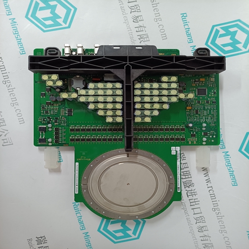
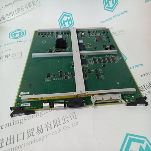
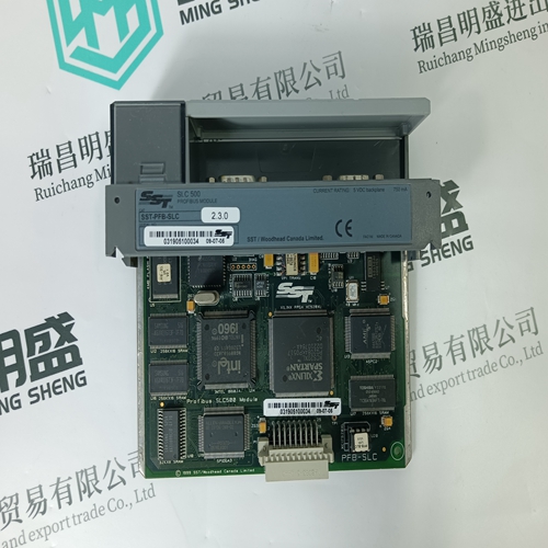
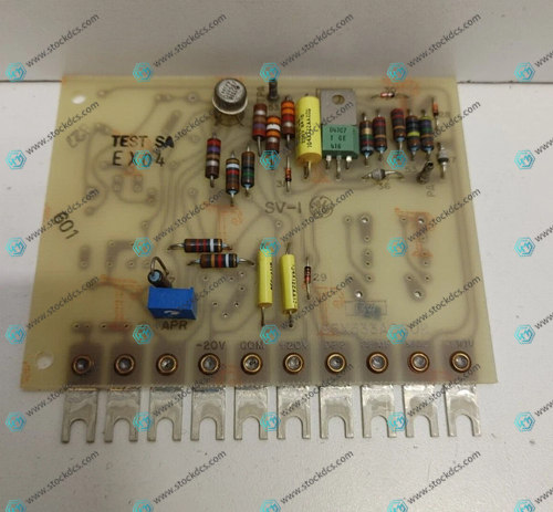
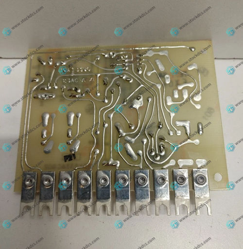
Product imag

Related website links
CI860K01 3BSE032444R1 power module
CI871AK01 3BSE092693R1 interface module
VE5010 Logic Controller Module
Other website links
ABB CHBX01R 2VAA008575R1 冗余模块底座
ABB GJR5251200R0202 07AI90-S D2 分析输入单元
| PMA43P-11100-00 | ANAT 0100-76091 | PFEA113 |
| PMA43P-10100-00 | AMAT 0100-00985 | PFTL 201D-100.0KN |
| PMA43P-00100-00 | AMAT 0100-00156 | PFEA113-IP65 3BSE050092R65 |
| PMA43N-Y0100-02 | AMAT 0100-20097 | PFTL101AE |
| PMA43N-11100-00 | AMAT 0100-00047 | PFTL 101B-10.0KN |
| PMA43N-10100-00 | AMAT 0100-02167 | PFRL101C |
| PMA43N-01100-00 | AMAT 0100-02131 | PFEA112 |
| PMA43N-00100-00 | AMAT 0100-00534 | PFTL101A-0.5 3BSE004160R1 0.5 |