Home > Product > PLC programmable module > 193X543ABG02 electric circuit board
193X543ABG02 electric circuit board
- Goods status: new/used
- Delivery date: stock
- The quality assurance period: 365 days
- Phone/WhatsApp/WeChat:+86 15270269218
- Email:stodcdcs@gmail.com
- Tags:
- Get the latest price:Click to consult
193X543ABG02 electric circuit board
Product Details Introduction
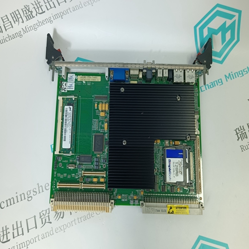
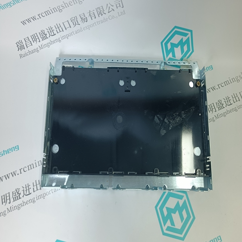
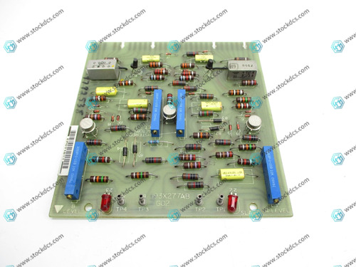
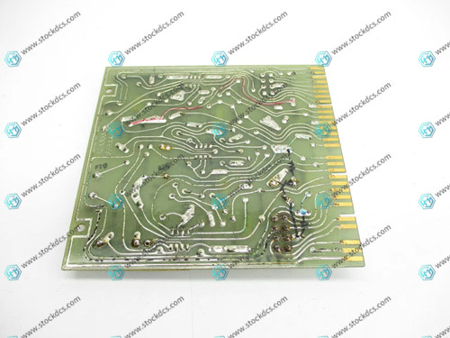
GE 193X543ABG02 is a critical circuit board in General Electric's 193X series industrial control systems, often referred to as an "electric control board" or "electric circuit board". This module is widely used in GE's DC or AC drive systems to execute control logic for electric equipment, including motor drive signal processing, feedback regulation, system protection, and other functions.
This circuit board is usually used as a sub functional board of the entire drive system, working together with the main control board, feedback board, excitation board, etc., to ensure the stable operation of the equipment on the industrial site.
Technical parameters and functional characteristics
Model: 193X543ABG02
Product type: Motor Control PCB
System adaptation: GE 193X series industrial automation system
Installation method: Standard card insertion installation, connected to the control framework through a gold finger interface
Input signals: analog signals (such as voltage feedback, current feedback), digital logic commands, trigger control signals
Output signal: Control signal output to actuators, drivers, relays, etc
Onboard components: integrated with multiple operational amplifiers, transistors, adjustable potentiometers, capacitors, resistors, and other standing element devices
Adjustment function: Equipped with a potentiometer for adjusting control gain, response time, compensation parameters, etc
Working voltage: usually ± 15V DC, requiring unified power supply from the system
Working temperature range: -20 ℃ to+70 ℃, suitable for industrial site environment
Status display: Some versions come with LED status indicators for easy debugging and operation monitoring
Application scenarios
GE Mark series industrial motor control system (such as Mark II, IV)
Large DC/AC motor drive equipment
Process control industries such as metallurgy, petrochemicals, power plants, water treatment, pulp and paper manufacturing, etc
Used to perform tasks such as motor start stop control, speed regulation, and status feedback processing
It is often used in the replacement or expansion of electric daughter boards in old GE control systems
Installation and usage precautions
Before installation, the system power must be disconnected to avoid short circuits or arcs during plugging and unplugging operations
The board is a static sensitive device, and an anti-static wristband should be worn during operation
All input and output signals should be strictly connected according to the system design drawings to prevent control logic abnormalities
Before the initial operation, a multimeter and oscilloscope can be used to check the voltage waveform and level of key test points
If the potentiometer needs to be adjusted, it should be slowly adjusted and the initial setting should be recorded in order to roll back the debugging value
It is recommended to conduct maintenance checks every 6-12 months, with a focus on issues such as capacitor aging, loose solder joints, and interface contact
Product imag

Related website links
KJ3222X1-BA1 Analog Input Module
Siemens 6ES7307-1EA01-0AA0 power module
Other website links
ABB UFC933A102 3BHE048062R0102 电路板
| PMA42N-00100-00 | AMAT 0100-00611 | PFTL 301E-0.5 |
| PMA42M-10100-00 | AMAT 0100-02797 | PFTL 301E-0.1 |
| PMA42M-01100-00 | AMAT 0100-14005 | PFTL 101BE-10.0KN |
| PMA42M-00100-00 | AMAT 0100-35082 | PFEA112-IP20 3BSE030369R0020 |
| PMA24K-1050B-02 | AMAT 0100-90139 | PFTL 101A-1.0KN |
| PMA24D-10100-00 | AMAT 0100-00642 | PFTL 301E-1.0KN |
| PMA24D-00100-00 | AMAT 0100-09292 | PFTL101A 1.0KN |
| PMA24C-11100-00 | AMAT 0100-00069 | PFTL 101BE-20.0KN |
| PMA24C-10100-00 | AMAT 0100-35170 | PFTL 101BER-10.0KN |