Home > Product > DCS control system > DSMB-01C 3AFE64691929 power supply board
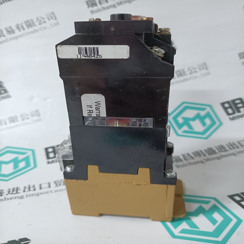
DSMB-01C 3AFE64691929 power supply board
- Product ID: DSMB-01C 3AFE64691929
- Brand: ABB
- Place of origin: The Swiss
- Goods status: new/used
- Delivery date: stock
- The quality assurance period: 365 days
- Phone/WhatsApp/WeChat:+86 15270269218
- Email:stodcdcs@gmail.com
- Tags:DSMB-01C 3AFE64691929power supply board
- Get the latest price:Click to consult
The main products
Spare parts spare parts, the DCS control system of PLC system and the robot system spare parts,
Brand advantage: Allen Bradley, BentlyNevada, ABB, Emerson Ovation, Honeywell DCS, Rockwell ICS Triplex, FOXBORO, Schneider PLC, GE Fanuc, Motorola, HIMA, TRICONEX, Prosoft etc. Various kinds of imported industrial parts
DSMB-01C 3AFE64691929 power supply board
To edit the hardware configuration of a Remote I/O Rack: 1. Select its icon in the left pane of the Network Configuration tool window. 2. On the Tools menu, click on Edit HW Configuration . This will start up the CIMPLICITY Control 90 Software. Information entered from the Network Configuration tool will already be in place. Settings for the FIP Remote I/O Scanner Select the Settings tab to configure the Remote I/O Scanner. Non-editable items for the Remote I/O Scanner include its Station ID and use of redundant media (dual bus cable). Configure the following additional parameters:Select External if the Remote I/O Scanner will receive a clock pulse signal via a cable attached to the front of the module. The Remote I/O Scanner receives a message containing the time and date from another FIP subscriber (usually a CPU) which is in charge of maintaining an accurate network time. The Remote I/O Scanner stores this information until it receives the next Synchro signal (via the Synchro cable). The Remote I/O Scanner then synchronizes its time-of-day clock.
Module Configuration in a Remote I/O Rack
The modules in the Remote I/O Scanner rack are configured in the normal manner for Series 90-30 I/O modules. Inputs and outputs in a Remote I/O Rack can be configured for additional FIP features, including blinking and chattering
Configuring a FIP Field Control Bus Interface Unit In a FIP network, a Field Control I/O Station that is interfaced to the network by a FIP Bus Interface Unit is also considered a type of remote I/O rack. Up to 8 Field Control modules can be accommodated in one I/O Station. BIU To edit the hardware configuration of a Field Control I/O Station, select its icon in the left pane of the Network Configuration tool window then choose TOOLS–EDIT HW CONFIGURATION. This will start up the CIMPLICITY Control 90 Software. Information entered from the Network Configuration tool will already be in place. To edit the hardware configuration of a Field Control I/O Station: 1. Select its icon in the left pane of the Network Configuration tool window. 2. On the Tools menu, click on Edit HW Configuration. This will start up the CIMPLICITY Control 90 Software. Information entered from the Network Configuration tool will already be in place. Configure the Bus Interface Unit and the I/O modules in the normal manner, as detailed in the BIU User’s Manual. There are no special parameters for Field Control products when used in a FIP network.