Home > Product > Gas turbine system > 531X303MCPBDG1 F31X303MCPA00300 card
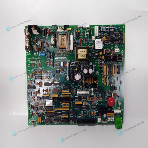
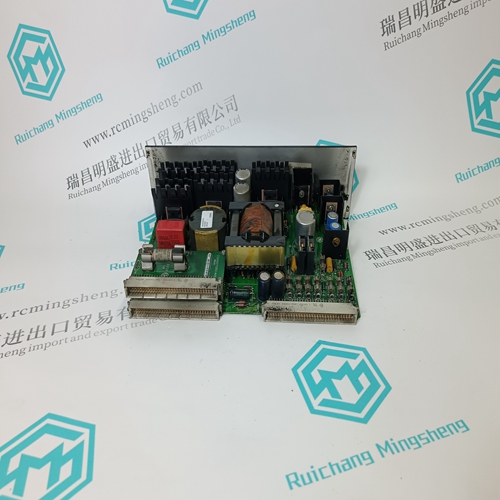
531X303MCPBDG1 F31X303MCPA00300 card
- Product ID: 531X303MCPBDG1 F31X303MCPA00300
- Brand: GE
- Place of origin: The United States
- Goods status: new/used
- Delivery date: stock
- The quality assurance period: 365 days
- Phone/WhatsApp/WeChat:+86 15270269218
- Email:stodcdcs@gmail.com
- Tags:531X303MCPBDG1F31X303MCPA00300card
- Get the latest price:Click to consult
531X303MCPBDG1 F31X303MCPA00300 card
Configuration of I/O Module Connections The following table shows two possible combinations of an I/O module, a pressure clamp terminal block, a terminal board, a relay board, and a signal cable: a pressure clamp terminal connection, and a dedicated signal cable connection. For the pressure clamp terminal connection and the MIL cable connection, the I/O module “For pressure clamp terminal block or MIL cable” must be used. For a dedicated signal cable connection, the I/O module “With signal cable interface adapter” must be used.
Variation of Signal Connection
Three kinds of connections are available for a wiring between an I/O module and field devices: a dedicated signal cable connection, a pressure clamp terminal connection, and an MIL cable connection. For the dedicated signal cable connection, the dedicated signal cable is used to connect field devices via a terminal board or a relay board. The signal cable interface adapter is structurally integrated with the I/O module. Wrong type I/O module insertion can be prevented by selecting an option code for I/O module and signal cables respectively. As for a pressure clamp terminal connection, field devices can be directly wired to I/O module. Two types of pressure clamp terminal blocks are available – one is a single configuration type and the other is a dual-redundant configuration type. The I/O module can be made dual redundant on the terminal block. The MIL cable, which is provided by a customer, can be connected directly to an I/O module without a terminal block. Preventing the MIL cable from being disconnected from the I/O module, cable connector covers (SCCC01 and SCCC02) are available for use with the MIL cable.
1: An I/O module has constraints
such as the magnitude of current or the cable length, depending on the connection
configuration. For more information, see “ProSafe-RS Outline of I/O Modules (for FIO)” (GS 32P06K60-01EN).
Note 2: Connect one terminal block for dual-redundant configuration to two adjacent I/O module.
Note 3: Cable connector covers (SCCC01 and SCCC02) are provided for the connection via a MIL connector cable.
Note 4: Do not ground the secondary side of a field power supply to be connected to the digital input module.
Note 5: When the input module is not individual insulation when the output of analog current output module (SAI533) is connected
directly with other input modules, it is necessary to put isolator between SAI533 and the input module.
*1: Relay read-back for DI module.
*2: When AKB331 is connected to SED3D, SBD3D or SBD4D, use AKB331 of style code S3.
*3: The style code and firmware revision numbers of SDV541 to be connected with SBM54D must be used following revision
or later

1.Payment method and delivery
Shipment: EMS,DHL,UPS & FEDEX
Payment: T/T or Western Union
2. About us
We are professional company and we are expert in this business, we have highly experienced production team, or sales team, or purchase team, we have most advanced production line. We are reputable in the market.
3. Application industry
Our main products are widely used in metallurgy, oil and gas, glass manufacturing, aluminum, petrochemical, coal mine, paper making and printing, textile printing and dyeing, machinery, electronic manufacturing, automobile manufacturing, tobacco, plastic machinery, electricity, water conservancy, water treatment/environmental protection, municipal engineering, boiler heating, energy, power transmission and distribution, etc.