Home > Product > Gas turbine system > GE WESDAC D20 C 504-0002-13 Gas turbine card
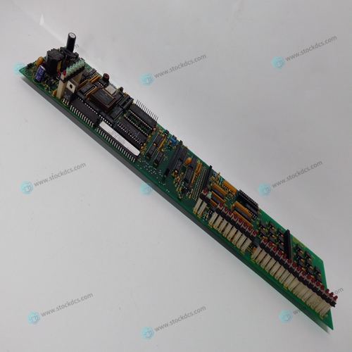
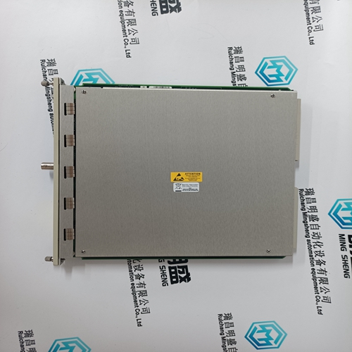
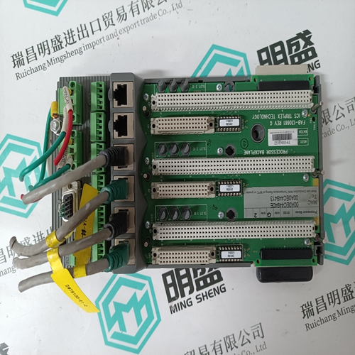
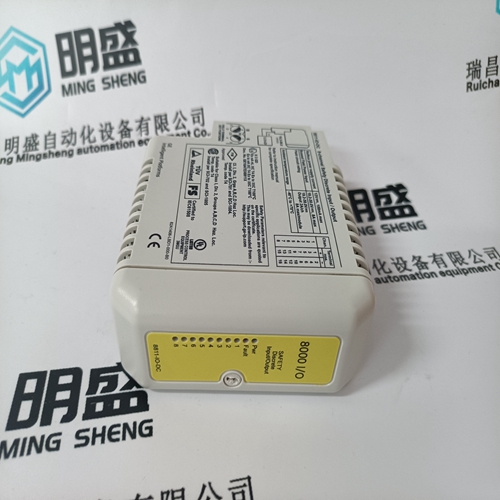
GE WESDAC D20 C 504-0002-13 Gas turbine card
- Product ID: WESDAC D20 C 504-0002-13
- Brand: GE
- Place of origin: The United States
- Goods status: new/used
- Delivery date: stock
- The quality assurance period: 365 days
- Phone/WhatsApp/WeChat:+86 15270269218
- Email:xiamen2018@foxmail.com
- Tags:GEWESDAC D20 C 504-0002-13Gas turbine card
- Get the latest price:Click to consult
GE WESDAC D20 C 504-0002-13 Gas turbine card
HIGH VOLTAGE—A high voltage across open CTs (current transformers) can cause death or serious injury. Do not disconnect a CT from the Load Sharing Module while the engine is running. The CTs can develop dangerously high voltages and may explode if open circuited while the engine is running. For this check, the generator set must be running isochronously, not paralleled, and with a power factor greater than 0.8. 10. Check that the potential connections are made as follows and correct them if they are not. Phase A to terminal 1 Phase B to Terminal 2 Phase C to Terminal 3 The most accurate calibration is made at full load. However, if it is not possible to run the generator set at full load, run it at less than full load, and reduce the voltage readings given in this calibration procedure proportionally. For example: run a 200 kW generator set at 100 kW and divide all voltages given in this calibration procedure by 2. If you reduce the load in this manner, be sure to reduce it the same amount throughout this calibration procedure.
Start the engine and apply full load to the generator set.
12. Using a dc voltmeter, measure the load signal at terminals 22 and 23. Adjust the load gain potentiometer to give a 6 Vdc load signal. If 6 Vdc is not obtainable, set the load signal as close as possible to 6 Vdc. Record this voltage. 13. Shut down the generator set. HIGH VOLTAGE—A high voltage across open CTs (current transformers) can cause death or serious injury. Do not disconnect a CT from the Load Sharing Module while the engine is running. The CTs can develop dangerously high voltages and may explode if open circuited while the engine is running.
Disconnect the wire from terminal
that comes from the phase “A” CT and connect both wires from this CT to terminal 4. 15. Start the generator set and apply full load. 16. Measure the load signal at terminals 22 and 23. If the phase “B” and “C” current transformers are connected correctly, this voltage will be 1/3 lower than the voltage recorded in step 13. For example: if the reading was 6 volts in step 13, the reading in this step should be approximately 4 volts. 17. Shut down the generator set. 18. Reconnect the phase “A” CT wire to terminal 5. 19. If the reading in step 16 was correct, proceed to Load Gain Adjustment later in this chapter. Otherwise, perform the following Phase Correction Procedure


About us
We are professional company and we are expert in this business, we have highly experienced production team, or sales team, or purchase team, we have most advanced production line. We are reputable in the market.
Superior products
-ABB Accuray
--ABB Advant OCS
--ABB Advant-800xA
--ABB H&B Contrans T
--ABB H&B Freelance 2000
--Allen Bradley PLC
--GE Ran card machine accessories,PLC
--ICS Triplex Rockwell T8151B/T8461/T8310
--Triconex/Foxboro:3625/3721/3503E/FBM237/FBM242
--Emerson:CE3008/VE3008/SE3008/A6120/A6312
--Motorola:MCP750/MVME162/MVME2604/MVME5100
--Woodward:9907-164/9907-167/9905-144/9905-018
The company is mainly engaged in above brands. You are welcome to inquire from me via email!
