Home > Product > PLC programmable module > PC-E984-685 Programmable control module
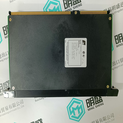
PC-E984-685 Programmable control module
- Product ID: PC-E984-685
- Brand: 140PLC
- Place of origin: The United States
- Goods status: new/used
- Delivery date: stock
- The quality assurance period: 365 days
- Phone/WhatsApp/WeChat:+86 15270269218
- Email:stodcdcs@gmail.com
- Tags:PC-E984-685Programmable control module
- Get the latest price:Click to consult
PC-E984-685 Programmable control module
If this procedure is followed, the correct connection of the current transformers is assured; the correct CT will be connected to the correct input on the Load Sharing Module with the correct polarity. Use this procedure only if the Phasing Check indicates that the phasing is incorrect. A CT for any phase (A, B, or C), will produce the most positive load signal voltage when it is connected, in the proper polarity, to the terminals on the Load Sharing Module which correspond to the same phase. Any other connections of this CT will produce a less positive load signal voltage. This procedure makes trial connections of the first CT to all three CT inputs on the Load Sharing Module, polarized both ways on each CT input. The load signal voltage is recorded for each connection, and the CT is then connected to the CT input terminals that produced the most positive load signal voltage and with the polarity that produced the most positive load signal voltage.
In a like manner
the second CT is tried on each of the two remaining CT input terminals in each polarity, then connected, in the correct polarity, to the terminals which produced the most positive load signal voltage. The remaining CT is then connected to the remaining CT input and the load signal checked for each polarity. This CT is then connected to the CT input, polarized so that it produces the most positive load signal voltage. When the procedure is completed, all three CTs are connected to the proper CT inputs on the Load Sharing Module, with the correct polarity, and are now labeled with their correct designations.
The procedure for correcting phase
wiring requires that the generator set be shut down and the current transformers disconnected many times. For convenience during the phasing check, the temporary method of connecting the current transformers shown in Figure 3-1 is recommended. By connecting a burden resistor (a 0.5 Ω, 20 W resistor), across each current transformer, that current transformer can be disconnected from the Load Sharing Module after removing all load. The connections between the terminal strip and the Load Sharing Module can be changed with the generator set running; however, remove all load before any changes in connections are made. Do not disconnect a wire from a current transformer with load on the system. After completion of the procedure remove the terminal strip and the resistors.

About us
We are professional company and we are expert in this business, we have highly experienced production team, or sales team, or purchase team, we have most advanced production line. We are reputable in the market.
Superior products
-ABB Accuray
--ABB Advant OCS
--ABB Advant-800xA
--ABB H&B Contrans T
--ABB H&B Freelance 2000
--Allen Bradley PLC
--GE Ran card machine accessories,PLC
--ICS Triplex Rockwell T8151B/T8461/T8310
--Triconex/Foxboro:3625/3721/3503E/FBM237/FBM242
--Emerson:CE3008/VE3008/SE3008/A6120/A6312
--Motorola:MCP750/MVME162/MVME2604/MVME5100
--Woodward:9907-164/9907-167/9905-144/9905-018
The company is mainly engaged in above brands. You are welcome to inquire from me via email!