Home > Product > PLC programmable module > ICS TRIPLEX T8310 control module
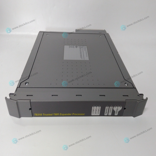
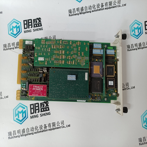
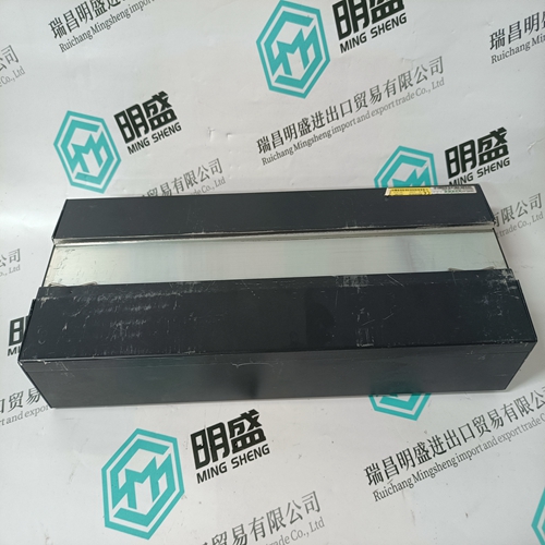
ICS TRIPLEX T8310 control module
- Product ID: T8310
- Brand: ICS TRIPLEX
- Place of origin: The United States
- Goods status: new/used
- Delivery date: stock
- The quality assurance period: 365 days
- Phone/WhatsApp/WeChat:+86 15270269218
- Email:stodcdcs@gmail.com
- Tags:ICS TRIPLEXT8310control module
- Get the latest price:Click to consult
ICS TRIPLEX T8310 control module
HIGH VOLTAGE—A high voltage across open CTs (current transformers) can cause death or serious injury. Do not disconnect a CT from the Load Sharing Module while the engine is running. The CTs can develop dangerously high voltages and may explode if open circuited while the engine is running. For this procedure, the generator set must be running isochronously, not paralleled, and with a power factor greater than 0.8. 1. Start with the generator shut down. 2. Label each CT wire with the phase and polarity that you think it should be. Even though this identification may prove to be wrong during this procedure, this step is necessary so that the individual wires may be identified during the description of the procedure.
3. Disconnect the phase “B” CT wires from terminals 6 and 7 and connect these two wires together. Use a small screw and nut and tape the connection. 4. Disconnect the phase “C” CT wires from terminals 8 and 9 and connect these two wires together. Use a small screw and nut and tape the connection. 5. Connect the two wires from the phase “A” CT to phase “A” input terminals 4 and 5.
When paralleled
adjustment of a generator set's LOAD GAIN potentiometer clockwise will cause that generator set to carry less load. If stability problems occur when paralleled at a particular load signal voltage, reduce the load signal voltage by adjusting the LOAD GAIN potentiometer counterclockwise and set the load signal voltage of all other generator sets in the system to the same voltage (NOTE—Adjust the LOAD GAIN with the generator running isochronously and not paralleled). When the load signal voltages of all generator sets in a system are reduced, the load sharing gain will be reduced. This may result in some loss of load-sharing sensitivity but will increase load sharing stability. It may be necessary to reduce the load signal voltage of each unit in the system to as low as three volts in cases of extremely poor system dynamics.
Droop Adjustment
Droop is usually expressed as a percentage. Droop percentage is calculated by dividing the difference between the no load speed and the full load speed by the rated speed. The DROOP potentiometer only needs to be adjusted when the generator set is to be operated in droop mode. The method of setting droop depends on whether the load on the generator set is an isolated load or an infinite bus. Once adjusted, the droop potentiometer will not have to be readjusted unless a different droop percentage is desired.

About us
We are professional company and we are expert in this business, we have highly experienced production team, or sales team, or purchase team, we have most advanced production line. We are reputable in the market.
Superior products
-ABB Accuray
--ABB Advant OCS
--ABB Advant-800xA
--ABB H&B Contrans T
--ABB H&B Freelance 2000
--Allen Bradley PLC
--GE Ran card machine accessories,PLC
--ICS Triplex Rockwell T8151B/T8461/T8310
--Triconex/Foxboro:3625/3721/3503E/FBM237/FBM242
--Emerson:CE3008/VE3008/SE3008/A6120/A6312
--Motorola:MCP750/MVME162/MVME2604/MVME5100
--Woodward:9907-164/9907-167/9905-144/9905-018
The company is mainly engaged in above brands. You are welcome to inquire from me via email!