Home > Product > DCS control system > PFEA111-65 3BSE050090R65 controller
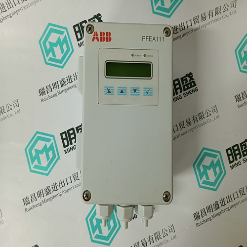
PFEA111-65 3BSE050090R65 controller
- Product ID: PFEA111-65 3BSE050090R65
- Brand: ABB
- Place of origin: The Swiss
- Goods status: new/used
- Delivery date: stock
- The quality assurance period: 365 days
- Phone/WhatsApp/WeChat:+86 15270269218
- Email:stodcdcs@gmail.com
- Tags:PFEA111-65 3BSE050090R65controller
- Get the latest price:Click to consult
The main products
Spare parts spare parts, the DCS control system of PLC system and the robot system spare parts,
Brand advantage: Allen Bradley, BentlyNevada, ABB, Emerson Ovation, Honeywell DCS, Rockwell ICS Triplex, FOXBORO, Schneider PLC, GE Fanuc, Motorola, HIMA, TRICONEX, Prosoft etc. Various kinds of imported industrial parts
PFEA111-65 3BSE050090R65 controller
The power supply provides 5 VDC to both the Main PCB and the Display PCB, and 12 VDC to the Main PCB. Verify the 12 VDC voltage is between 11.7 and 12.3 volts when measured from Pin 5 (+V) to Pin 3 or 4 (Ground). Verify the 5 VDC voltage is between 4.9 and 5.1 volts when measured from Pin 1 (+5V) to Pin 3 or 4 (Ground), and Pin 2 to Pin 3 or 4 (Ground). If the voltages are absent or deviate from the specified range, replace the Power Supply PCB. See Figure 3-11 for the H location and description of Pins 1, 2, 3, 4 and 5 on the Power Supply harness.If setup parameters change uncontrollably or programming is lost, check the BRAM battery voltage. Battery voltage is tested at the battery assembly on the Main PCB. The battery is shown in Figure 3-13.Use a Volt-Ohm meter to measure voltage between terminal 1 (positive) and terminal 2 (negative) to the left and right of the battery with the AC power disconnected. This measurement should be approximately 3.0 VDC. Replace the battery (Panasonic CR2032 or comparable) if the measured voltage is below 2.5 VDC.The battery replacement procedure is detailed in the Maintenance > Run section of Chapter 3, Configuration.
RS-232 Serial Output Voltage Test
If the send and receive functions of the serial (COM) ports test fail, use the following procedure to determine whether the RS-232 serial port is operational: 1. Disconnect AC power from both the IND780 terminal and the printer. 2. Disconnect the serial cable from the COM port on the IND780 main PCB. 3. Set the voltmeter to read 20 VDC. 4. Connect the red lead to the transmit terminal of the COM port and connect the black lead to the ground terminal of the COM port. 5. Apply power to the IND780. The meter should read as follows: • Demand mode—The meter should read a stable value (without fluctuation) between −5 and +15 VDC. • Continuous mode—The meter should fluctuate continuously within the range −10 to +10 VDC. The actual values and degree of fluctuation observed will depend on the type and sensitivity of meter used. The constant fluctuation on the meter display indicates that the scale/indicator is transmitting information. To test Demand baud rates, press the PRINT key . The display should fluctuate as for continuous mode for the duration of the transmission, then become stable again. This fluctuation indicates the terminal has transmitted data. When measuring the higher baud rates in the Demand mode, the meter display will fluctuate for a shorter period of tim