Home > Product > DCS control system > PFEA112-65 control
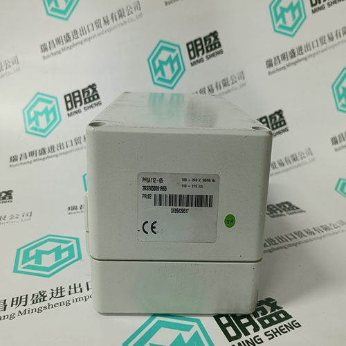
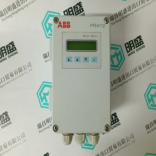
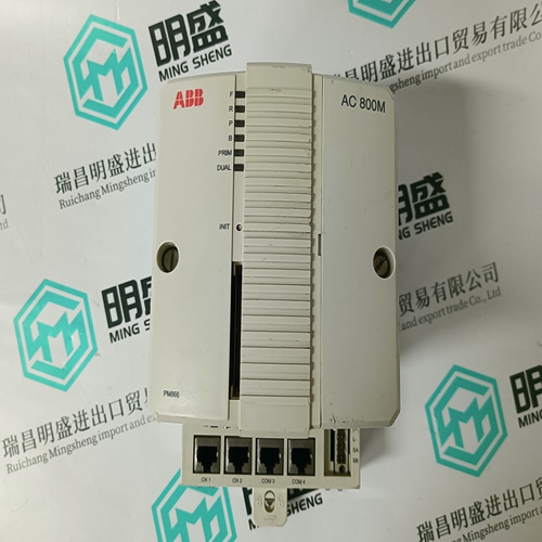
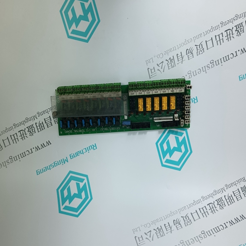
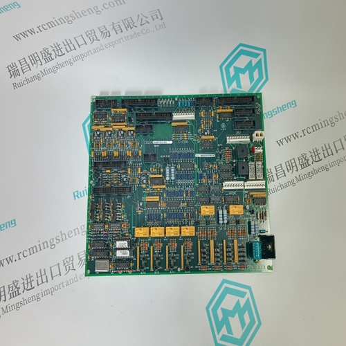
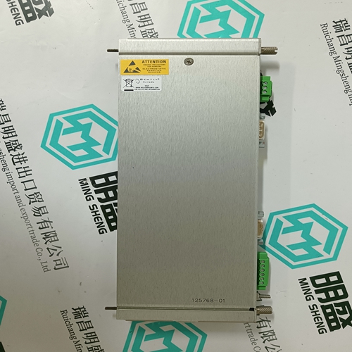
PFEA112-65 control
- Product ID: PFEA112-65
- Brand: ABB
- Place of origin: The Swiss
- Goods status: new/used
- Delivery date: stock
- The quality assurance period: 365 days
- Phone/WhatsApp/WeChat:+86 15270269218
- Email:stodcdcs@gmail.com
- Tags:PFEA112-65control
- Get the latest price:Click to consult
The main products
Spare parts spare parts, the DCS control system of PLC system and the robot system spare parts,
Brand advantage: Allen Bradley, BentlyNevada, ABB, Emerson Ovation, Honeywell DCS, Rockwell ICS Triplex, FOXBORO, Schneider PLC, GE Fanuc, Motorola, HIMA, TRICONEX, Prosoft etc. Various kinds of imported industrial parts
PFEA112-65 control
Internal Diagnostic Testing The IND780 provides several internal diagnostic tests that are accessible in setup mode. Press the SETUP softkey to view the setup menu tree. Use the DOWN navigation key to scroll down the menu tree to Maintenance. Press the RIGHT navigation key to expand the menu tree selections for Maintenance. Scroll down and expand Run. Scroll down and expand Diagnostics. Available diagnostic setup screens are shown in the setup tree view in HFigure 3-15.Load Cell Output—Displays the current load cell output (active weight) for the scale ( HFigure 3-19). The numbers in the scale below feature load cell addresses for each output. For digital load cells, individual cell counts will be displayed. Individual cell counts are the raw output of the load cells, which the indicator translates into weight by calculation, using information it acquires through the calibration process.Calibration Values—Displays the current calibration values for each scale ( HFigure 3-20). If these values are recorded after a scale calibration, and the scale channel PCB is replaced in the future, the calibration values can be manually entered here to “transfer” the previous calibration to the new scale channel PCB. This is not available with IDNet bases.
Shift Values—Used for POWERCELL scales only.
The following screen
shows values used to adjust gain for each load cell in a multiple load
cell system. The values compensate for difference in response between
cells. The load cell numbers represent the node cell addresses. Where
more than 12 load cells are present this screen displays a scroll box to
reveal further rows.
The diagnostic purpose of the Load Cell Output and Shift Values screens is to
permit a technician to confirm valid calibration values were obtained when the
calibration routine (Setup > Scale > Scale n > Calibration) was carried out.
Statistics—Displays statistical information for each scale such as the total number of weighments, the number of scale overloads, the peak weight weighed on the scale, the total number of zero commands, and failed zero commands ( Figure 3-22). These are very helpful when H diagnosing scale problems. These statistics accumulate for each scale, and are saved until a master reset is performed. It is not considered likely that a master reset will be a frequent occurrence, so these statistics are effectively permanent. Statistics cannot be deleted without losing all other setup values.
