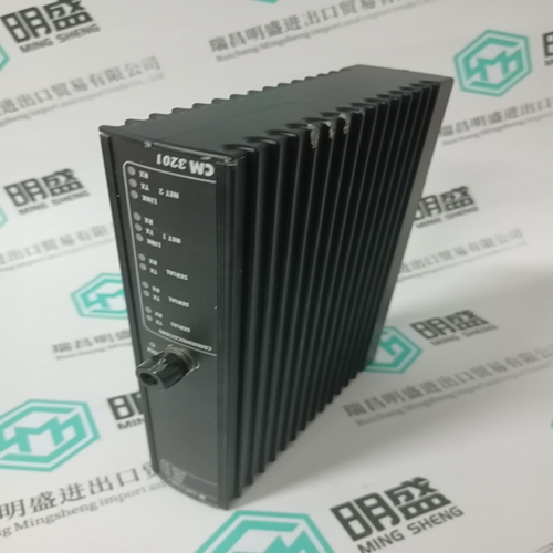
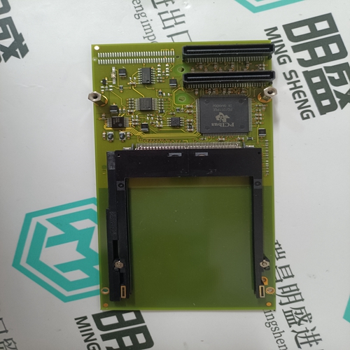
Home > Product > DCS control system > CMA131 3DDE300411 Industrial control module
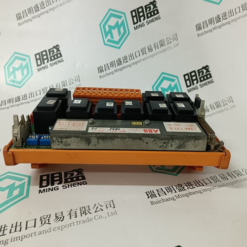
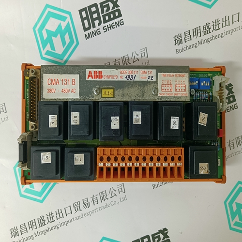
CMA131 3DDE300411 Industrial control module
- Product ID: CMA131 3DDE300411
- Brand: ABB
- Place of origin: The Swiss
- Goods status: new/used
- Delivery date: stock
- The quality assurance period: 365 days
- Phone/WhatsApp/WeChat:+86 15270269218
- Email:stodcdcs@gmail.com
- Tags:CMA131 3DDE300411Industrial control module
- Get the latest price:Click to consult
The main products
Spare parts spare parts, the DCS control system of PLC system and the robot system spare parts,
Brand advantage: Allen Bradley, BentlyNevada, ABB, Emerson Ovation, Honeywell DCS, Rockwell ICS Triplex, FOXBORO, Schneider PLC, GE Fanuc, Motorola, HIMA, TRICONEX, Prosoft etc. Various kinds of imported industrial parts
CMA131 3DDE300411 Industrial control module
Master Reset A hardware master reset switch is provided, that sets all IND780 terminal settings to the factory default settings (see Appendix B, Default Settings). This includes scale setup and calibration information, log files (except for the error log) and counters. The master reset typically is performed under these circumstances: • When a hardware configuration change is made, such as adding a new scale or Discrete I/O board to the terminal. • When a software configuration problem arises that cannot be resolved without starting from the factory default settings. • When security is enabled to protect setup, and the password is lost. • After a firmware upgrade is performed. • After a hardware key is installed or removed. Two types of master reset are possible, depending on the position of switch S2 (shown in its OFF position in Figure 3-37): A full reset including metrologically significant scale configuration data, and a reset that preserves scale data. To initiate a master reset, perform the following steps: 1. Remove AC power. 2. If the reset is to include scale configuration data, set S2 to its ON position. If scale configuration data are to be retained, leave S2 OFF. 3. Press and hold the MASTER RESET button (Figure 3-37).
Main PCB Removal
To remove a main PCB from an IND780, follow these steps: 1. Remove AC power. 2. Use a grounding strap to prevent risk of electrostatic discharge. 3. At the back of the terminal, identify and label all option board cables. 4. Disconnect the option board cables and power cable from the back of the terminal. 5. It may not be necessary to remove the panel mount from its location. If removal is required: A. Use an 8 mm nut driver to remove the eight nuts securing the terminal to its mounting location. B. Remove the backing plate and lift the terminal out of the opening in which it is installed. 6. Open the terminal by removing its rear cover (in the case of a panel mount terminal) or its front panel (in the case of a harsh environment terminal). 7. Remove the two screws attaching the upper card guide, shown in Figure 3-38, H and lift the guide from its stand-offs.The option board connector pins are delicate. Take care to avoid damaging them when removing the boards. 8. Note the locations of the option boards then remove them and set them aside on a static-free mat . Disconnect any PLC interface module cables or connectors from their sockets.
Apply AC power. Hold the MASTER RESET button until the unit beeps and the “BRAM reset to Factory” message pops up. 5. Press ENTER to acknowledge each message box as it appears. 6. If S2 was set to ON to include metrologically significant data in the reset, return it to its OFF position.
