Home > Product > DCS control system > CMA132 3DDE300412 control module


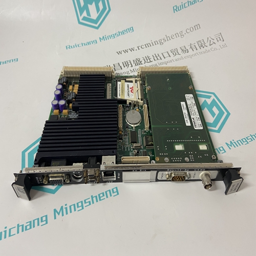
CMA132 3DDE300412 control module
- Product ID: CMA132 3DDE300412
- Brand: ABB
- Place of origin: The Swiss
- Goods status: new/used
- Delivery date: stock
- The quality assurance period: 365 days
- Phone/WhatsApp/WeChat:+86 15270269218
- Email:stodcdcs@gmail.com
- Tags:CMA132 3DDE300412control module
- Get the latest price:Click to consult
The main products
Spare parts spare parts, the DCS control system of PLC system and the robot system spare parts,
Brand advantage: Allen Bradley, BentlyNevada, ABB, Emerson Ovation, Honeywell DCS, Rockwell ICS Triplex, FOXBORO, Schneider PLC, GE Fanuc, Motorola, HIMA, TRICONEX, Prosoft etc. Various kinds of imported industrial parts
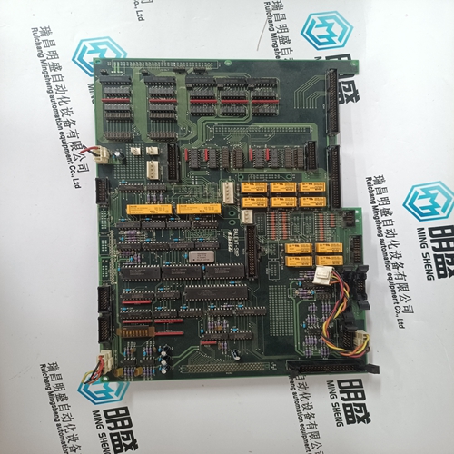
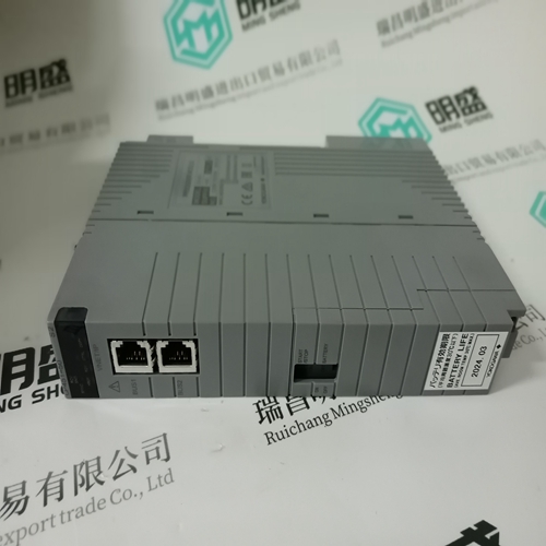
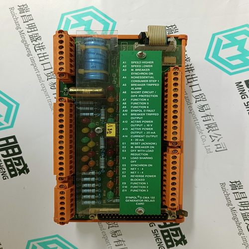
CMA132 3DDE300412 control module
For a panel mount terminal, install screws in the center holes and in the four hex post stand-offs in the outer holes (see Figure 3-41). H B. For a harsh enclosure terminal, install six screws. 3. Reconnect all peripherals – COM1, COM2, Ethernet, USB, power and video. 4. Install option boards as necessary. 5. Reconnect the PLC interface module cable or connectors if appropriate. 6. Replace the rear cover or front panel.ETX Board Installation This procedure must be performed with the main PCB removed from the IND780 enclosure: All mounting screws should be installed with 23 inch pounds (2.6 Nm) of torque. To install an ETX board on the main PCB: 1. Note the orientation of the ETX board indicated in Figure 3-43. The ETX H connectors are arranged so that it cannot be installed backwards. 2. Position the ETX board over its connectors. HFigure 3-44 shows two of the connectors, and Figure 3-45 shows a side view of the board resting on its H connectors.With the main PCB resting flat on a static-free mat, press down firmly over each ETX board connector to seat it. The connectors seat with an audible snap. Note that simply installing the ETX board mounting screws will not seat the connectors properly – see HFigure 3-45. Each connector must be pressed into place.Install screws to secure the board to the main PCB. Two of these screws also attach the lower card guide. This bar is asymmetrical, and must be mounted in the orientation indicated in HFigure 3-47. Note that the longer end is oriented toward the main PCB battery.
CF Card Removal and Installation
To remove a CF card from the ETX board, hold the sides of the CF card and carefully slide it out of its socket, in the direction indicated in Figure 3-47. It may H be necessary to move the card slightly side to side to disengage it.To install a CF card in the ETX board, slide the CF card into its socket, in the direction indicated in HFigure 3-48. Keep the card straight, to avoid damaging the socket’s pins. The card will snap into place. There are two guides on the CF Card. One is thinner than the other. Do not force the CF Card into the carrier.Power Supply Removal Components in the power supply may be hot to the touch. Allow them to cool before performing the procedure described below. To remove a power supply: 1. Disconnect the incoming power cord and the cord from the main PCB from their connectors on the power supply board. These connectors are keyed and can only be attached in the correct orientation. In Figure 3-49 they are shown H attached and in HFigure 3-50 they are shown disconnected.Use a 7 mm nut driver to remove the nut and washer (indicated in HFigure 3-50) from each of the two posts holding the power supply bracket to the enclosure. In a panel mount terminal this bracket is mounted beside the main PCB. In a harsh enclosure terminal, the bracket is mounted to one end wall of the enclosure.Lift the bracket and power supply out of the enclosure. 4. Remove the power supply PCB from the bracket by removing the four screws, one at each corner, visible in HFigure 3-50.