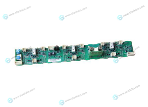
Home > Product > PLC programmable module > 140CRA31200 Motion module
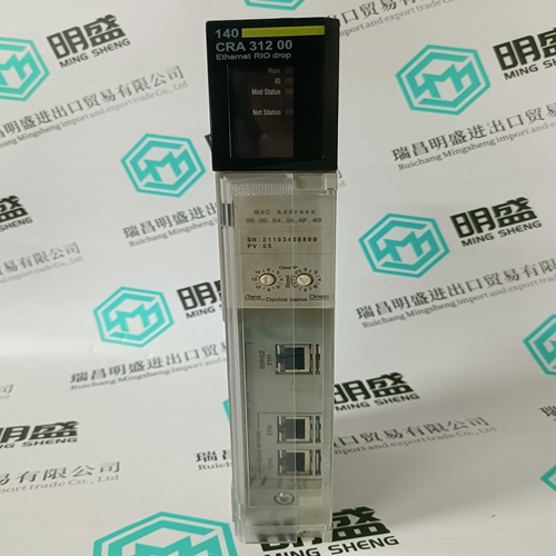
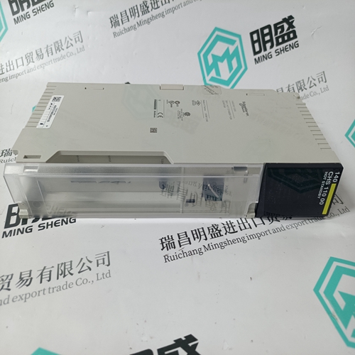
140CRA31200 Motion module
- Product ID: 140CRA31200
- Brand: 140PLC
- Place of origin: the United States
- Goods status: new/used
- Delivery date: stock
- The quality assurance period: 365 days
- Phone/WhatsApp/WeChat:+86 15270269218
- Email:stodcdcs@gmail.com
- Tags:140CRA31200Motion module
- Get the latest price:Click to consult
The main products
Spare parts spare parts, the DCS control system of PLC system and the robot system spare parts,
Brand advantage: Allen Bradley, BentlyNevada, ABB, Emerson Ovation, Honeywell DCS, Rockwell ICS Triplex, FOXBORO, Schneider PLC, GE Fanuc, Motorola, HIMA, TRICONEX, Prosoft etc. Various kinds of imported industrial parts
140CRA31200 Motion module
Physical dimensions and required cutout dimensions for the PQMII are shown below. Once the cutout and mounting holes are made in the panel, use the eight #6 self-tapping screws provided to secure the PQMII. Mount the unit on a panel or switchgear door to allow operator access to the keypad and indicators.Product attributes vary according to the configuration and options selected on the customer order. Before applying power to the PQMII, examine the label on the back and ensure the correct options are installed. The following section explains the information included on the label shown below:• Model No: Shows the PQMII configuration. The model number for a basic panel mount PQMII is “PQMII”. T20, C, and A appear in the model number only if the Transducer, Control, or Power Analysis options are installed. • Supply Voltage: Indicates the power supply input configuration installed in the PQMII. The PQMII shown in this example can accept any AC 50/60Hz voltage from 70 to 265 V AC or DC voltage from 90 to 300 V DC. • Tag#: An optional identification number specified by the customer. • Mod#: Indicates if any unique features have been installed for special customer orders. This number should be available when contacting GE Multilin for technical support. • Version: An internal GE Multilin number that should be available when contacting us for technical support. • Serial No.: Indicates the serial number in numeric and barcode formats. Record this number when contacting GE Multilin for technical support.
Revision History
The PQMII revision history is shown below. Each instruction manual revision corresponds to a particular firmware revision. The manual revision is located on the title page as part of the manual part number (the format is 1601-nnnn-revision). The firmware revision is loaded in the PQMII and can be viewed by scrolling to the A4 PRODUCT INFO ÖØ SOFTWARE VERSIONS ÖØ MAIN PROGRAM VERSION message. When using the instruction manual to determine PQMII features and settings, ensure that the instruction manual revision corresponds to the firmware revision installed in the PQMII using the table below.
Signal wiring is to Terminals 21 to 51. These terminals accommodate wires sizes up to 12 gauge. Please note that the maximum torque that can be applied to terminals 21 to 51 is 0.5 Nm (or 4.4 in ·lb.). CT, VT, and control power connections are made using Terminals 1 to 20. These #8 screw ring terminals accept wire sizes as large as 8 gauge. Consult the wiring diagrams for suggested wiring. A minimal configuration includes connections for control power, phase CTs/VTs, and the alarm relay; other features can be wired as required. Considerations for wiring each feature are given in the sections that follow.
