Home > Product > PLC programmable module > 5136-DNP-PCI Drive module card
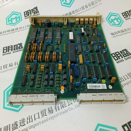
5136-DNP-PCI Drive module card
- Product ID: 5136-DNP-PCI
- Brand: SST
- Place of origin: the United States
- Goods status: new/used
- Delivery date: stock
- The quality assurance period: 365 days
- Phone/WhatsApp/WeChat:+86 15270269218
- Email:xiamen2018@foxmail.com
- Tags:5136-DNP-PCIDrive module cardSST
- Get the latest price:Click to consult
The main products
Spare parts spare parts, the DCS control system of PLC system and the robot system spare parts,
Brand advantage: Allen Bradley, BentlyNevada, ABB, Emerson Ovation, Honeywell DCS, Rockwell ICS Triplex, FOXBORO, Schneider PLC, GE Fanuc, Motorola, HIMA, TRICONEX, Prosoft etc. Various kinds of imported industrial parts
5136-DNP-PCI Drive module card
The 2½ element 4-wire wye connection can be used for situations where cost or size restrictions limit the number of VTs to two. With this connection, Phase Vbn voltage is calculated using the two existing voltages. Select the S2 SYSTEM SETUP ÖØ CURRENT/VOLTAGE CONFIGURATION ÖØ VT WIRING: “4 WIRE WYE (2 VTs)” setpoint. This wiring configuration will only provide accurate power measurements if the voltages are balanced.
3-wire System using Two CTs The figure below shows two methods for connecting CTs to the PQMII for a 3-wire system. The top drawing shows the standard wiring configuration using three CTs. An alternate wiring configuration uses only two CTs. With the two CT method, the third phase is measured by connecting the commons from phase A and C to the phase B input on the PQMII. This causes the phase A and phase C current to flow through the PQMII’s phase B CT in the opposite direction, producing a current equal to the actual phase B current.The control power supplied to the PQMII must match the installed power supply. If the applied voltage does not match, damage to the unit may occur. Check the product identification to verify the control voltage matches the intended application.
Control Power
A universal AC/DC power supply is standard on the PQMII. It covers the range 90 to 300 V DC and 70 to 265 V AC at 50/60 Hz. It is not necessary to adjust the PQMII if the control voltage is within this range. A low voltage power supply is available as an option. It covers the range 20 to 60 V DC and 24 to 48 V AC at 50/60 Hz. Verify from the product identification label that the control voltage matches the intended application. Connect the control voltage input to a stable source for reliable operation. A 2.5 A HRC fuse is accessible from the back of the PQMII via the fuse access door. Consult the factory for replacement fuses, if required. Using #12 gauge wire or ground braid, connect Terminals 5 and 6 to a solid system ground, typically a copper bus in the switchgear. The PQMII incorporates extensive filtering and transient protection to ensure reliable operation under harsh industrial operating environments. Transient energy must be conducted back to the source through Filter Ground Terminal (5). The Filter Ground Terminal (5) is separated from the Safety Ground Terminal (6) to allow dielectric testing of switchgear with the PQMII wired up. Filter Ground Terminal connections must be removed during dielectric testing. When properly installed, the PQMII meets the interference immunity requirements of IEC 801 and ANSI C37.90.1.


