Home > Product > DCS control system > P0916PH P0916AL Terminal module
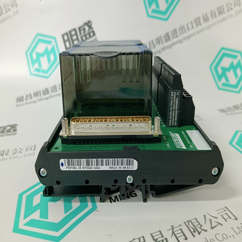
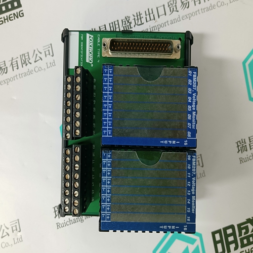
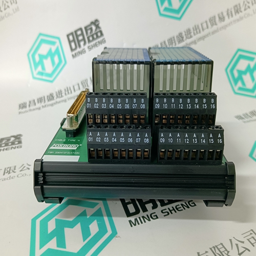
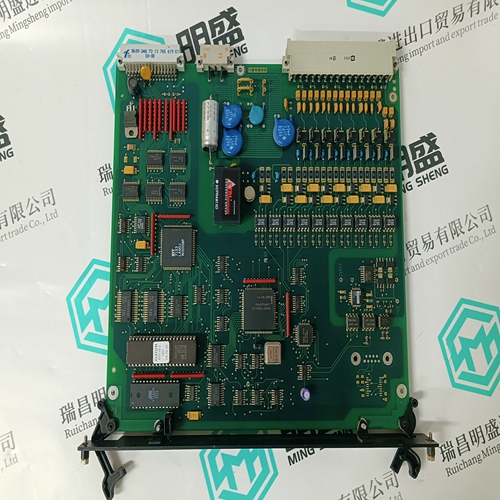
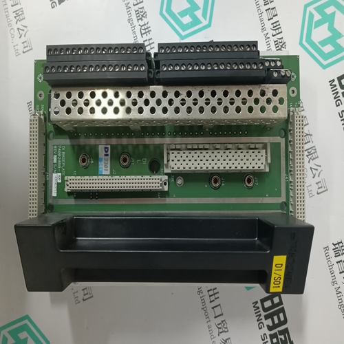
P0916PH P0916AL Terminal module
- Product ID: P0916PH P0916AL
- Brand: FOXBORO
- Place of origin: The United States
- Goods status: new/used
- Delivery date: stock
- The quality assurance period: 365 days
- Phone/WhatsApp/WeChat:+86 15270269218
- Email:stodcdcs@gmail.com
- Tags:P0916PH P0916ALTerminal module
- Get the latest price:Click to consult
The main products
Spare parts spare parts, the DCS control system of PLC system and the robot system spare parts,
Brand advantage: Allen Bradley, BentlyNevada, ABB, Emerson Ovation, Honeywell DCS, Rockwell ICS Triplex, FOXBORO, Schneider PLC, GE Fanuc, Motorola, HIMA, TRICONEX, Prosoft etc. Various kinds of imported industrial parts
P0916PH P0916AL Terminal module
Analog Input (Optional) Terminals 22(–) and 23(+) are provided for a current signal input. This current signal can be used to monitor any external quantity, such as transformer winding temperature, battery voltage, station service voltage, transformer tap position, etc. Any transducer output ranges within the range of 0 to 20 mA can be connected to the analog input terminals of the PQMII. See 5.3.3: Analog Input for details on programming the analog input.
The last PQMII in the chain and the master computer require a terminating resistor and terminating capacitor to ensure proper electrical matching of the loads and prevent communication errors. Using terminating resistors on all the PQMIIs would load down the communication network while omitting them at the ends could cause reflections resulting in communication errors. Install the 120 Ω, ¼ watt terminating resistor and 1 nF capacitor externally. Although any standard resistor and capacitor of these values are suitable, these components can also be ordered from GE Multilin as a combined terminating network. Each communication link must have only one computer (PLC or DCS) issuing commands called the master. The master should be centrally located and can be used to view actual values and setpoints from each PQMII called the slave device. Other GE Multilin relays or devices using the Modbus RTU protocol can be connected to the communication link. Setpoints in each slave can also be changed from the master. Each PQMII in the link must be programmed with a different slave address prior to running communications using the S1 PQMII SETUP ÖØ COM1 RS485 SERIAL PORT ÖØ MODBUS COMMUNICATION ADDRESS setpoint. The GE Multilin EnerVista PQMII Setup Software may be used to view status, actual values, and setpoints. See 4.4: Using the EnerVista PQMII Setup Software for more information on the EnerVista PQMII Setup Software
RS232 Front Panel Port
A 9-pin RS232C serial port provided on the front panel allows the user to program the PQMII with a personal computer. This port uses the same communication protocol as the rear terminal RS485 ports. To use this interface, the personal computer must be running the EnerVista PQMII Setup Software provided with the relay. Cabling to the RS232 port of the computer is shown below for both 9-pin and 25-pin connectors.
Dielectric Strength Testing It may be required to test the complete switchgear for dielectric strength with the PQMII installed. This is also known as “flash” or “hipot” testing. The PQMII is rated for 1500 V AC isolation between relay contacts, CT inputs, VT inputs, control power inputs and Safety Ground Terminal 6. Some precautions are necessary to prevent damage to the PQMII during these tests. Filter networks and transient protection clamps are used between the control power, serial port, switch inputs, analog outputs, analog input, and the filter ground terminal 5 to filter out high voltage transients, radio frequency interference (RFI) and electromagnetic interference (EMI). The filter capacitors and transient absorbers could be damaged by the continuous high voltages relative to ground that are applied during dielectric strength testing. Disconnect the Filter Ground (Terminal 5) during testing of the control power inputs. Relay contact and CT terminals do not require any special precautions. Do not perform dielectric strength testing on the serial ports, switch inputs, analog input or analog output terminals or the PQMII internal circuitry will be damaged.
