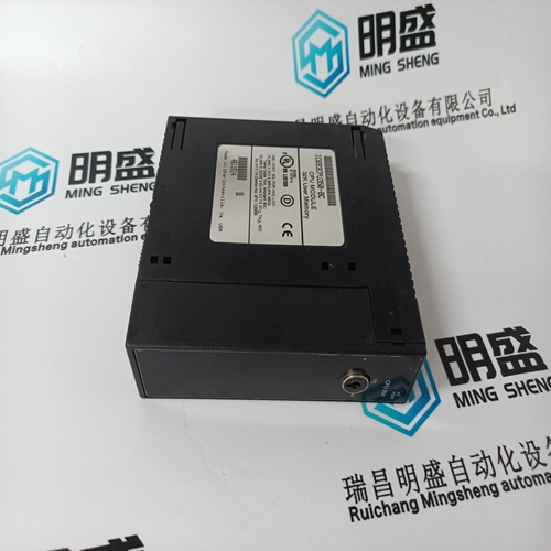
Home > Product > Gas turbine system > 369-HI-0-M-0-0-0-E Relay module
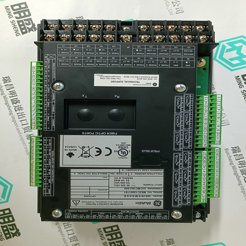
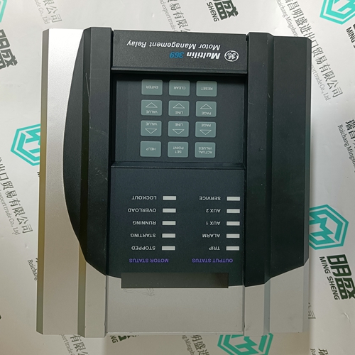
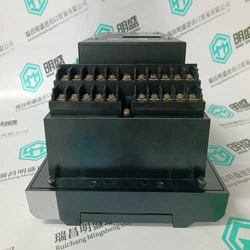
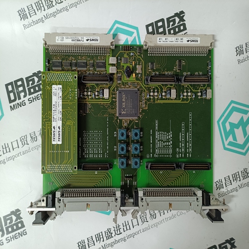
369-HI-0-M-0-0-0-E Relay module
- Product ID: 369-HI-0-M-0-0-0-E
- Brand: GE
- Place of origin: the United States
- Goods status: new/used
- Delivery date: stock
- The quality assurance period: 365 days
- Phone/WhatsApp/WeChat:+86 15270269218
- Email:stodcdcs@gmail.com
- Tags:369-HI-0-M-0-0-0-ERelay module
- Get the latest price:Click to consult
The main products
Spare parts spare parts, the DCS control system of PLC system and the robot system spare parts,
Brand advantage: Allen Bradley, BentlyNevada, ABB, Emerson Ovation, Honeywell DCS, Rockwell ICS Triplex, FOXBORO, Schneider PLC, GE Fanuc, Motorola, HIMA, TRICONEX, Prosoft etc. Various kinds of imported industrial parts
369-HI-0-M-0-0-0-E Relay module
The window includes details of the currently selected harmonic and other harmonic analysis-related data (for example, THD, K Factor, etc.). Z Select Read Last Trigger From Device to load previous acquired spectra from the PQMII. 4.5.3 Trace Memory The trace memory feature allows the PQMII to be setup to trigger on various conditions. The trace memory can record maximum of 36 cycles of data (16 samples per cycle) for all voltage and current inputs simultaneously. A Total Trace Triggers Counter has been implemented in the PQMII Memory Map at Register 0x0B83. This register will keep a running total of all valid Trace Memory Triggers from the last time power was applied to the PQMII. The Total Trace Triggers counter will rollover to 0 at 65536. The trace memory feature is implemented into the EnerVista PQMII Setup Software as shown below. Z Select the Setpoint > PQMII Setup > Trace Memory Setup menu item to setup the trace memory feature.
Data Logger
The data logger feature allows the PQMII to continuously log various specified parameters at the specified rate. The data logger uses the 64 samples/cycle data. This feature is implemented into EnerVista PQMII Setup Software as shown below. Z Select the Setpoint > System Setup > Data Log menu item to setup the data logger feature. This launches the Data Log settings box shown below. The state of each data logger and percent filled is shown. Z Use the Start Log 1(2) and Stop Log 1(2) buttons to start and stop the logs.
The Trace Memory Usage parameter is set as follows: • 1 x 36 cycles: upon trigger, the entire buffer is filled with 36 cycles of data • 2 x 18 cycles: 2 separate 18-cycle buffers are created and each is filled upon a trigger • 3 x 12 cycles: 3 separate 12 cycle buffers are created and each is filled upon a trigger If the Trace Memory Trigger Mode is set to “One-Shot”, then the trace memory is triggered once per buffer; if it is set to “Retrigger”, then it automatically retriggers and overwrites the previous data. The Trace Memory Trigger Delay delays the trigger by the number of cycles specified. The Voltage, Current, and Switch Inputs selections are the parameters and levels that are used to trigger the trace memory. Clicking Save sends the current settings to the PQMII.
