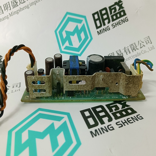
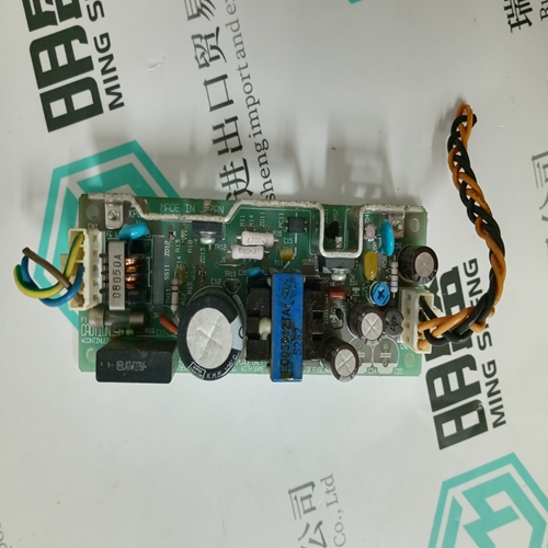
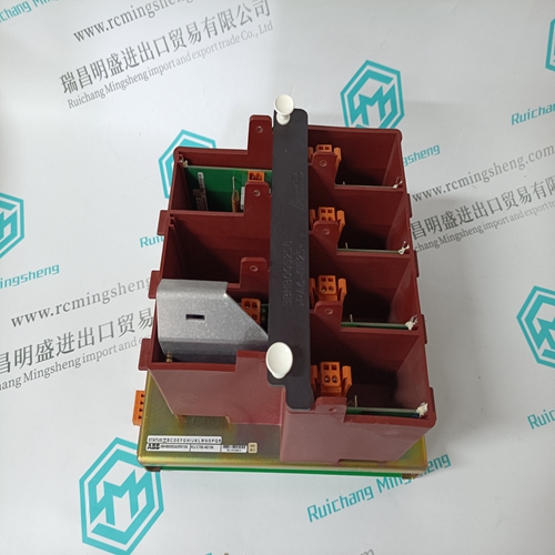
Home > Product > Robot control system > CAUTION 3L046-5 KPC CG Channel isolation module
CAUTION 3L046-5 KPC CG Channel isolation module
- Product ID: 3L046-5 KPC CG
- Brand: CAUTION
- Place of origin: the United States
- Goods status: new/used
- Delivery date: stock
- The quality assurance period: 365 days
- Phone/WhatsApp/WeChat:+86 15270269218
- Email:stodcdcs@gmail.com
- Tags:CAUTION3L046-5 KPC CGChannel isolation module
- Get the latest price:Click to consult
The main products
Spare parts spare parts, the DCS control system of PLC system and the robot system spare parts,
Brand advantage: Allen Bradley, BentlyNevada, ABB, Emerson Ovation, Honeywell DCS, Rockwell ICS Triplex, FOXBORO, Schneider PLC, GE Fanuc, Motorola, HIMA, TRICONEX, Prosoft etc. Various kinds of imported industrial parts
CAUTION 3L046-5 KPC CG Channel isolation module
The Log 1(2) Mode parameters are set as follows: • “Run to Fill”: when the data logger is full (100%) it will stop logging • “Circulate”: when the data logger is full, it will start from the beginning and overwrite the previous data. 2. The Log 1(2) Interval parameters determine how frequently the PQMII logs each piece of data. 3. The total log size is approximately 192KB. The allotment of this memory can be varied between the two logs to maximize the overall log time. Set the Log Size Determination to let the PQMII automatically optimize the memory. If desired, the optimization can also be performed manually by the user. 4. The Log 1(2) Fill Time parameters represent the amount of time the data logger takes to fill to 100%. This time is dependent on the logging interval and the number of parameters being logged. Z Set the parameters to be logged by setting the various Log Assignment parameters to the desired log. Z Select the Actual > Power Analysis > Data Logger > Log 1 (or Log 2) item to view the respective data logger.The Data Log 1(2) dialog box displays the record numbers, data log start time, the current time, and parameter values for the current cursor line position.
Voltage Disturbance Recorder
The Voltage Disturbance Recorder allows the PQMII to monitor and record sag and swell disturbances. This function can record up to 500 sag/swell events for all voltages simultaneously. The events roll-over and old events are lost when more than 500 events are recorded. Note PQMII VDR events are stored in volatile memory. Therefore, all voltage disturbance events will be cleared when control power is cycled to the meter. The operation of the voltage disturbance recorder as implemented in the EnerVista PQMII Setup Software is shown below: Z Select the Setpoint > System Setup > System Config menu item. Z Select the Voltage Disturbance Recorder Setup tab. Z The Sag Level % Nominal should be set to the level to which a voltage input must fall before a sag event is to be recorded. The Swell Level % Nominal should be set to the level to which a voltage input must rise before a swell event is to be recorded. Z Click Save to send the current settings to the PQMII
