Home > Product > DCS control system > ABB PFTL201CE weighing sensor
ABB PFTL201CE weighing sensor
- Product ID: PFTL201CE
- Brand: ABB
- Place of origin: The Swiss
- Goods status: new/used
- Delivery date: stock
- The quality assurance period: 365 days
- Phone/WhatsApp/WeChat:+86 15270269218
- Email:stodcdcs@gmail.com
- Tags:ABBPFTL201CEweighing sensor
- Get the latest price:Click to consult
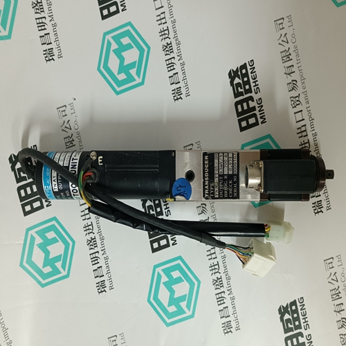
ABB PFTL201CE weighing sensor
Connection Method
1. Strip the insulation of the power lines used.
2. Open the terminal block wiring insertion area with a tool. There are two opening methods as shown in figures A and B. • Figure A shows opening by prying with an accessory lever. • Figure B shows opening by forcibly pressing the driver insertion aperture with either a flathead screwdriver head width 3.0~3.5mm (.118~.138 in.) or a 210-120Jtype driver from Wago, Inc.
3. Insert the core of the power line into the opening. Release the lever or the pressure on the driver after insertion.
Note 1 Do not use empty terminals for relays.
Note 2 Connect the I/O signal cable shield wire to the connector shell. This is connected to the frame ground on the digital torque amplifier side connector.
Interface Circuit
An example is given below of connection of the digital torque amplifier I/O signals to an upper level device. ■ Command Input Circuit and Interface Analog Input Circuit The analog signal is the torque reference signal. The input impedance is as follows. • Command Input (CMD-IN): Approx. 14kΩ The maximum allowable voltage for the input signal is ±12V • 10V= Peak Motor Torque This is connected by a relay or open collector transistor circuit. Select a low current type when connecting by relay. If low current relay is not used, this may cause a connection fault.
Output Circuits and Interfaces
The output signal circuits of the digital torque amplifier are of the three types shown below. Configure the input circuit on the upper-level device to match each of these output circuits. • Connection with Line Driver Output Circuits The output signals (PAO, *PAO, PBO, *PBO) where the encoder serial data was converter to a 2-phase (A-phase, B-phase) pulse, and the origin pulse signal (PCO, *PCO) are output by the line driver circuit. The upper-level device receives these through the line receiver circuit. See “2.3 Wiring to the Encoder” for an example of the connection circuit. • Connection with Photocoupler Output Circuit Servo alarms and other output signals for sequence use are configured in the photocoupler output circuit. They are connected through the relay and line driver circuits.

Do you want to know about our products?
We have a large amount of inventory and high quality, out of production control system components, DCS system accessories, robot system accessories, large servo system spare parts. PLC module, DCS module, CPU module, IO module, DO module, AI module, DI module, network communication module, Ethernet module, motion control module, analog input module, analog output module, digital input module, digital output module, redundancy module, power module, relay output module, relay input module, processor module and other major brands.