Home > Product > PLC programmable module > NI CFP-AI-111 analog input module
NI CFP-AI-111 analog input module
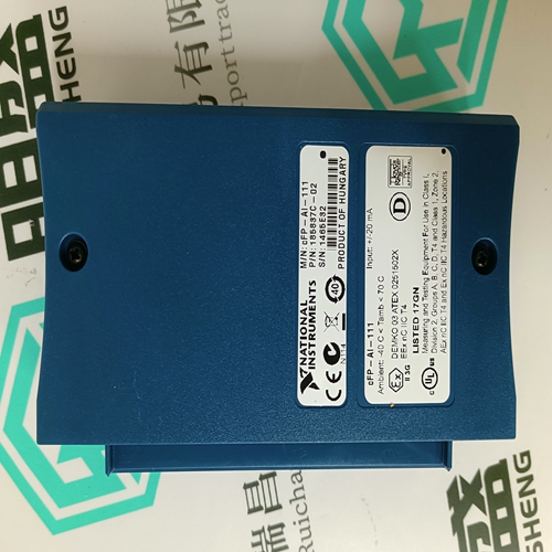
- Product ID: CFP-AI-111
- Brand: NI
- Place of origin: the United States
- Goods status: new/used
- Delivery date: stock
- The quality assurance period: 365 days
- Phone/WhatsApp/WeChat:+86 15270269218
- Email:stodcdcs@gmail.com
- Tags:NICFP-AI-111analog input module
- Get the latest price:Click to consult
The main products
Spare parts spare parts, the DCS control system of PLC system and the robot system spare parts,
Brand advantage: Allen Bradley, BentlyNevada, ABB, Emerson Ovation, Honeywell DCS, Rockwell ICS Triplex, FOXBORO, Schneider PLC, GE Fanuc, Motorola, HIMA, TRICONEX, Prosoft etc. Various kinds of imported industrial parts
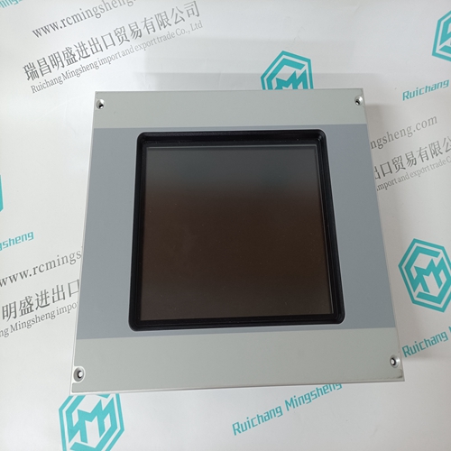
NI CFP-AI-111 analog input module
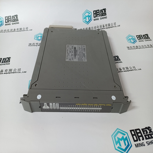
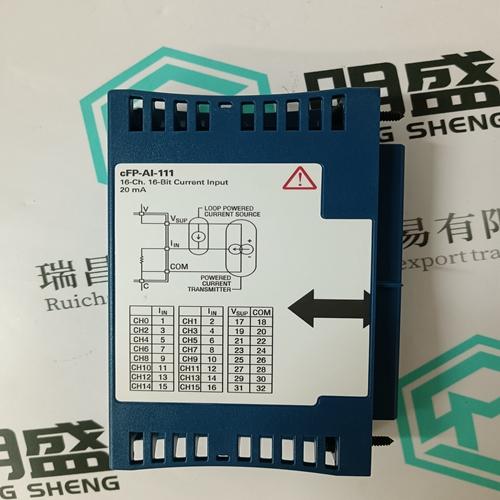
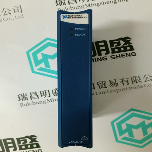
16, 16 channels, Compact FieldPoint current analog input module - the cFP - AI - 111 have outrange alarms and on-board diagnosis function, to ensure that the correct installation and maintenance. The mold piece is used for onboard measurement and linearization of signal and the conversion of value is returned to the control or monitoring software.
Z Enter the desired site name in the Site Name field. If desired, a short description of site can also be entered along with the display order of devices defined for the site. Z Click the OK button when complete. The new site will appear in the upper-left list in the EnerVista PQMII Setup Software window. Z Click the Add Device button to define the new device. Z Enter the desired name in the Device Name field and a description (optional) of the site. Z Select the appropriate communications interface (Ethernet or Serial) and fill in the required information for the PQMII.Z Click the Read Order Code button to connect to the PQMII device and upload the order code. If a communications error occurs, ensure that communications values entered in the previous step correspond to the relay setting values. Z Click OK when complete. Z From the EnerVista main window, select the IED Dashboard item to open the Plug and Play IED dashboard. An icon for the PQMII will be shown.
Setpoint Entry Methods
Prior to operating the PQMII, it is necessary to program setpoints to define system characteristics and alarm settings by one of the following methods: • Front panel, using the keys and display. • Rear terminal RS485 port COM1 or COM2, or front RS232 port and a computer running the EnerVista PQMII Setup Software included with the PQMII, or from a SCADA system running user-defined software. Either of the above methods can be used to enter the same information. However, a computer makes information entry considerably easier. Moreover, a computer allows setpoint files to be stored and downloaded for fast, error-free entry. The EnerVista PQMII Setup Software included with the PQMII facilitates this process. With this software, setpoints can be modified remotely and downloaded at a later time to the PQMII. Refer to 4.4: Using the EnerVista PQMII Setup Software for additional details. Setpoint messages are organized into logical groups or pages for easy reference. Messages may vary somewhat from those illustrated because of installed options, and messages associated with disabled features will be hidden. This context sensitive operation eliminates confusing detail. Before accurate monitoring can begin, the setpoints on each page should be worked through, entering values either by local keypad or computer. The PQMII leaves the factory with setpoints programmed to default values. These values are shown in all setpoint message illustrations. Many of these factory default values can be left unchanged. At a minimum, however, setpoints that are shown shaded in 5.3.1: Current and Voltage Configuration must be entered for the system to function correctly. As a safeguard, the PQMII will alarm and lock-out until values have been entered for these setpoints. The CRITICAL SETPOINTS NOT STORED alarm message will be displayed until the PQMII is programmed with these critical setpoints.