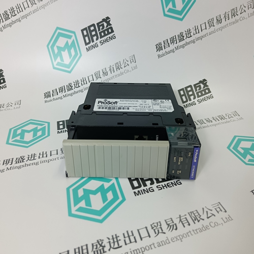
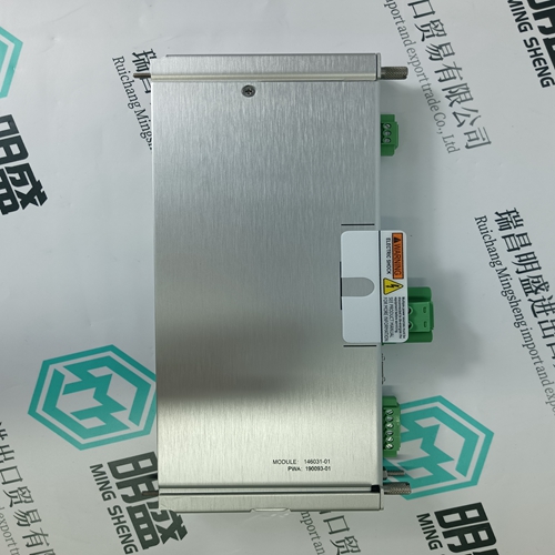
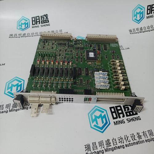
Home > Product > Robot control system > NEC 136-551733-B-02 Output circuit module
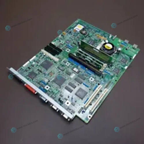
NEC 136-551733-B-02 Output circuit module
- Product ID: 136-551733-B-02
- Brand: NEC
- Place of origin: The United States
- Goods status: new/used
- Delivery date: stock
- The quality assurance period: 365 days
- Phone/WhatsApp/WeChat:+86 15270269218
- Email:stodcdcs@gmail.com
- Tags:NEC136-551733-B-02Output circuit module
- Get the latest price:Click to consult
NEC 136-551733-B-02 Output circuit module
This is the normal status of the controller. A routine, which has been loaded into the controller, is executed. The controller processes input and output signals, carries out communication, and performs hardware and software tests. Flashing The controller is in STOP mode and is not executing a routine. All system outputs are reset. STOP mode can be triggered by setting the Emergency stop system variable to TRUE in the routine, or by direct command from the programming software. Off The controller is in ERROR_STOP mode (see ERROR).No upload of controller configuration or operating system in progress. FORCE On The controller is executing a routine (RUN) and FORCE mode is activated by the user. Flashing The controller is in STOP mode, but Forcing has been initiated and will be activated when the controller is started.
• A hardware error has been detected by the controller.
The controller goes to ERROR_STOP mode and the execution of the routine is halted. Hardware errors are errors in the controller, errors in one or more of the digital input and output modules, or errors in the counters.
• A software error in the operating system has been detected by the controller.
• The watchdog has reported an error due to exceeded cycle time. All system outputs will be reset and the controller ceases all hardware and software tests. The controller can only be restarted by a command from the programming software. Off No errors are detected. PROGress On The upload of a new controller configuration is in progress. Flashing The upload of a new operating system into the nonvolatile ROM is in progress.
• The routine (logic) has caused an error.
• The controller configuration is faulty.
• The upload of a new operating system was not successful and the operating system is corrupted. Flashing An error has occurred during a nonvolatile ROM write cycle. One or more I/O errors have occurred. Off None of the above errors has occurred. OSL Flashing Emergency Operating System Loader is active. BL Flashing Boot Loader unable to load operating system or unable to start COMM operating system loader. Module status can be interrogated through the programming software. For more information, refer to the GuardPLC System User Manual, publication 1753-UM001.


Do you want to know about our products?
We have a large amount of inventory and high quality, out of production control system components, DCS system accessories, robot system accessories, large servo system spare parts. PLC module, DCS module, CPU module, IO module, DO module, AI module, DI module, network communication module, Ethernet module, motion control module, analog input module, analog output module, digital input module, digital output module, redundancy module, power module, relay output module, relay input module, processor module and other major brands.
