Home > Product > Robot control system > NEC 136-553623-A-01 Serial control module
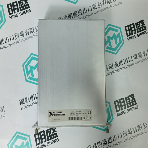
NEC 136-553623-A-01 Serial control module
- Product ID: 136-553623-A-01
- Brand: NEC
- Place of origin: The United States
- Goods status: new/used
- Delivery date: stock
- The quality assurance period: 365 days
- Phone/WhatsApp/WeChat:+86 15270269218
- Email:xiamen2018@foxmail.com
- Tags:NEC136-553623-A-01Serial control module
- Get the latest price:Click to consult
NEC 136-553623-A-01 Serial control module
After determining which category applies to your 1747-DCM application:
1. Find the column for the scanner used in your application.
2. Go down the column to the chassis address that you assigned to the 1747-DCM.
3. Use the switch settings in the right-most columns of the table that correspond to your chassis address
The starting I/O group number must be an even number from 0 to 6 (e.g. 0, 2, 4, or 6) and is dependent upon whether the 1747-DCM has been configured as a full, ¾, ½, or ¼ chassis. The first word transferred is always the status word for the 1747-DCM. The table below shows the switch settings for the starting I/O group numbers.
Direct Communication Module
Turn the switch to the OFF position if you want the 1747-DCM to clear and hold clear all data bits in its input image table in the event of an RIO communication failure or when the supervisory processor enters the Program/Test/Fault mode. Status bits will not be cleared. Turn the switch to the ON position if you want the 1747-DCM to hold all input data bits in their last state if an RIO communication failure occurs or when the supervisory processor enters the Program/Test/Fault mode.Before setting SW2-3 to ON, make sure that holding all 1747-DCM input bits in their last state, in the event of an RIO communication failure, does not create an unsafe condition in the distributed SLC processor.
Last Chassis (SW2-4)
Switch SW2-4 must be set to the OFF position if the 1747-DCM shares its logical chassis with at least one other adapter and has been assigned the highest I/O group number in that logical chassis.
The logical chassis size allocates image space in the scanner for each 1747-DCMs I/O data. The 1747-DCM allows ¼, ½, ¾, and full chassis addressing. SW2 switches 5 and 6 define the chassis size, as shown below.The 1747-DCM image cannot cross logical chassis boundaries. For example, configuring the module for ½ logical chassis with starting group 6 will cause a configuration error.Make sure you have set the DIP switches properly before installing the 1747-DCM. See Module Configuration on page 7.

Do you want to know about our products?
We have a large amount of inventory and high quality, out of production control system components, DCS system accessories, robot system accessories, large servo system spare parts. PLC module, DCS module, CPU module, IO module, DO module, AI module, DI module, network communication module, Ethernet module, motion control module, analog input module, analog output module, digital input module, digital output module, redundancy module, power module, relay output module, relay input module, processor module and other major brands.