Home > Product > Robot control system > NEC FC-9821KE Bus expansion module
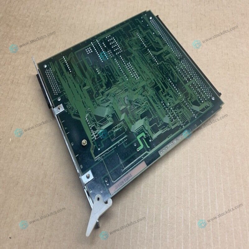
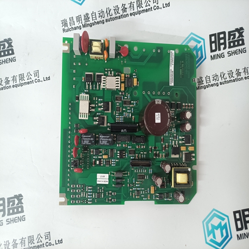
NEC FC-9821KE Bus expansion module
- Product ID: FC-9821KE
- Brand: NEC
- Place of origin: The United States
- Goods status: new/used
- Delivery date: stock
- The quality assurance period: 365 days
- Phone/WhatsApp/WeChat:+86 15270269218
- Email:xiamen2018@foxmail.com
- Tags:NECFC-9821KEBus expansion module
- Get the latest price:Click to consult
NEC FC-9821KE Bus expansion module
RIO scanner’s processor in Program/Test/Fault mode Check for RIO scanner’s processor error, correct condition, and cycle power to the 1747-DCM. Off RIO scanner’s processor not connected to scanner Check that the scanner is properly installed in the chassis. RIO scanner’s processor chassis inhibited Check RIO scanner’s processor chassis integrity, correct any problem, and cycle power to the 1747-DCM. No communication between RIO scanner’s processor and 1747-DCM Check that the baud rate of the 1747-DCM matches the baud rate of the scanner. Check cable connections from the RIO scanner or its processor to the 1747-DCM. Check that the 1747-DCM connector is properly installed.
Memory Module Installation
Always turn off power to the controller before removing the processor and inserting the memory module. This guards against possible damage to the module and undesired processor faults. Memory modules have connectors that are “keyed” to guard against improper installation.To avoid potential damage to the memory modules, handle them by the ends of the carrier or edges of the plastic housing. Skin oil and dirt can corrode metallic surfaces, inhibiting electrical contact. Also, do not expose memory modules to surfaces or areas that may typically hold an electrostatic charge. Electrostatic charges can alter or destroy memory.
Modular Controller
If the processor module is installed in the chassis, turn off power to the controller.
2. Remove the module by pressing the retainer clips at both the top and bottom of the module and sliding it out.
3. Locate the socket on the 1747-L511, -L514, and -L524 processor boards or the connector on the 1747-L531, -L532, -L541, -L542, -L542P, -L543, -L543P, -L551, -L552, -L553, and -L553P processor boards. Place the memory module onto the socket or connector and press firmly in place.
4. Place jumper J1 as shown above on the -L514 and -L524 processors.
5. Install the processor module into the chassis.
6. Restore power to the controller.


Do you want to know about our products?
We have a large amount of inventory and high quality, out of production control system components, DCS system accessories, robot system accessories, large servo system spare parts. PLC module, DCS module, CPU module, IO module, DO module, AI module, DI module, network communication module, Ethernet module, motion control module, analog input module, analog output module, digital input module, digital output module, redundancy module, power module, relay output module, relay input module, processor module and other major brands.
