Home > Product > Gas turbine system > GE VMIVME-7765 Gas turbine interface module
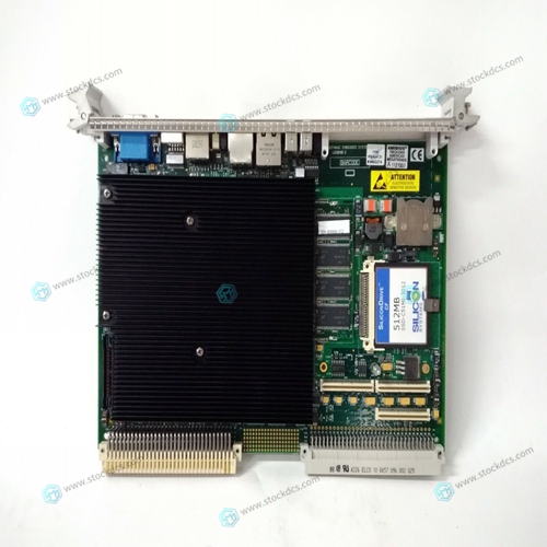
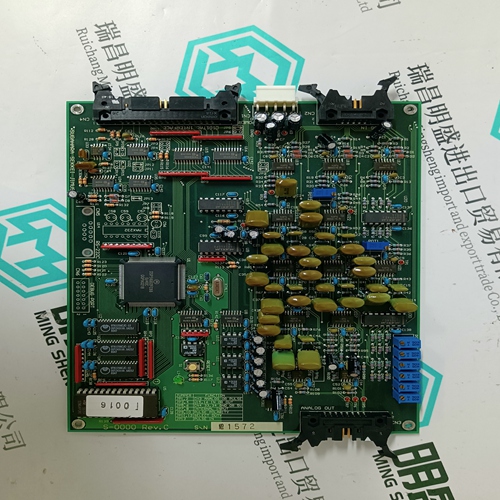
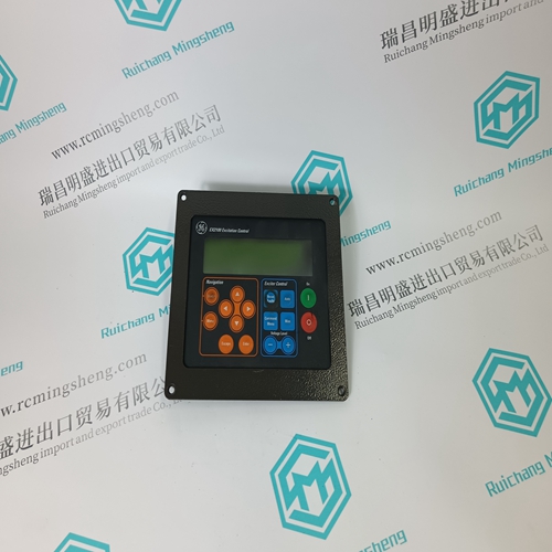
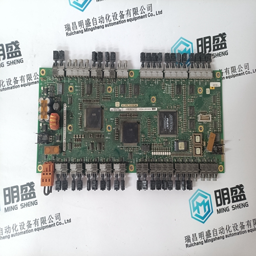
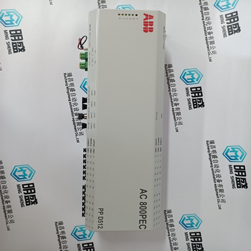
GE VMIVME-7765 Gas turbine interface module
- Product ID: VMIVME-7765
- Brand: GE
- Place of origin: The United States
- Goods status: new/used
- Delivery date: stock
- The quality assurance period: 365 days
- Phone/WhatsApp/WeChat:+86 15270269218
- Email:xiamen2018@foxmail.com
- Tags:GEVMIVME-7765Gas turbine interface module
- Get the latest price:Click to consult
GE VMIVME-7765 Gas turbine interface module
When using shielded cable, ground the foil shield and drain wire only at one end of the cable. We recommend that you wrap the foil shield and drain wire together and connect them to a chassis mounting bolt (Figure 2.4). At the opposite end of the cable, tape exposed shield and drain wire with electrical tape to insulate it from electrical contact.
Possible module fault causes and corrective action are discussed in the chapter titled “Troubleshooting.”In this chapter you learned how to install your input module in an existing programmable controller system and how to wire to the field wiring arm.
Installing the Module
When installing your module in an I/O chassis: 1. First, turn off power to the I/O chassis: ! ATTENTION: Remove power from the 1771 I/O chassis backplane and wiring arm before removing or installing an I/O module. Failure to remove power from the backplane could cause injury or equipment damage due to possible unexpected operation. Failure to remove power from the backplane or wiring arm could cause module damage, degradation of performance, or injury. 2. Place the module in the plastic tracks on the top and bottom of the slot that guides the module into position. 3. Do not force the module into its backplane connector. Apply firm even pressure on the module to seat it properly.
Interpreting the Indicator Lights
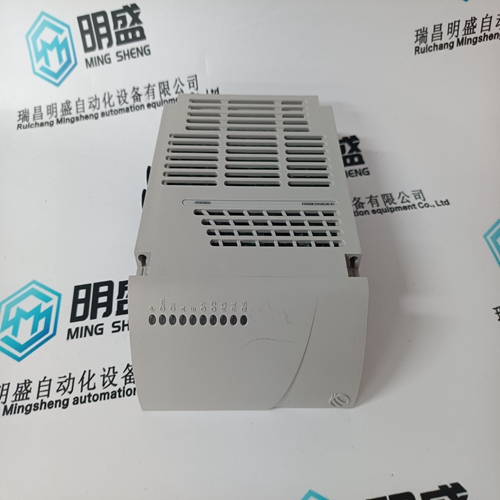
The front panel of the input module contains 12 input indicators, 8 output indicators, an active indicator and a fault indicator (Figure 2.5). At power-up, the active and fault indicators are on. An initial module self-check occurs. If there is no fault, the red indicator turns off. If a fault is found initially or occurs later, the fault indicator lights and the active indicator is forced off. When an input LED (A, B) is on, it indicates that the input is high. When the output LED is on, it indicates that the module has commanded the output to be on. When a gate/reset indicator (G) is on, its input is high. Since that signal can be inverted, it does not indicate whether the signal on that terminal is necessarily logically true.


Do you want to know about our products?
We have a large amount of inventory and high quality, out of production control system components, DCS system accessories, robot system accessories, large servo system spare parts. PLC module, DCS module, CPU module, IO module, DO module, AI module, DI module, network communication module, Ethernet module, motion control module, analog input module, analog output module, digital input module, digital output module, redundancy module, power module, relay output module, relay input module, processor module and other major brands.
