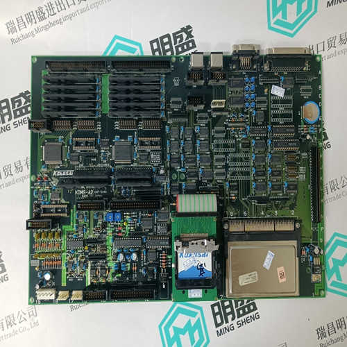
Home > Product > PLC programmable module > NI-9505 Acquisition card module
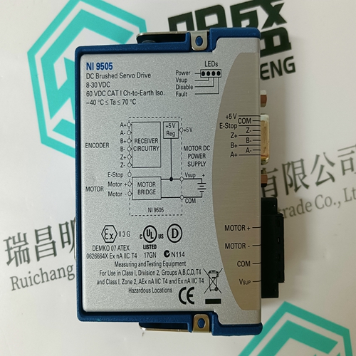
NI-9505 Acquisition card module
- Product ID: NI-9505
- Brand: NI
- Place of origin: the United States
- Goods status: new/used
- Delivery date: stock
- The quality assurance period: 365 days
- Phone/WhatsApp/WeChat:+86 15270269218
- Email:stodcdcs@gmail.com
- Tags:NI-9505Acquisition card module
- Get the latest price:Click to consult
The main products
Spare parts spare parts, the DCS control system of PLC system and the robot system spare parts,
Brand advantage: Allen Bradley, BentlyNevada, ABB, Emerson Ovation, Honeywell DCS, Rockwell ICS Triplex, FOXBORO, Schneider PLC, GE Fanuc, Motorola, HIMA, TRICONEX, Prosoft etc. Various kinds of imported industrial parts
NI-9505 Acquisition card module
The Event Recorder can be disabled or enabled using the EVENT RECORDER OPERATION setpoint. When the Event Recorder is disabled no new events are recorded. When the Event Recorder is enabled new events are recorded with the 150 most recent events displayed in A3 POWER ANALYSIS ÖØ EVENT RECORDER. Refer to 6.4.4 Event Recorder for the list of possible events. All data within the Event Recorder is stored in non-volatile memory.metering calculations is done on top of the trace memory sampling. The harmonic analysis sampling (256 samples/cycles, 1 cycle) causes the trace memory sampling to stop for one cycle whenever a harmonic analysis is requested. Refer to 4.5.3 Trace Memory for details on trace memory implementation in the EnerVista PQMII Setup Software. • TRACE MEMORY USAGE: The trace memory feature allows the user to capture maximum of 36 cycles. The TRACE MEMORY USAGE setpoint allows the buffer to be divided into maximum of 3 separate buffers as shown in table below.
The trace memory will be triggered once per buffer as defined in the TRACE MEMORY USAGE setpoint above. In order for it to re-trigger, it must be re-armed through the serial port using the EnerVista PQMII Setup Software or other software. Once rearmed the trace memory will default back to the first buffer
Ia/Ib/Ic/In OVERCURRENT TRIG LEVEL
Once the phase A/B/C/neutral current equals or increases above this setpoint value, the trace memory is triggered and data on all inputs are captured in the buffer. The number of cycles captured depends on the value specified in the TRACE MEMORY USAGE setpoint. • Va/Vb/Vc OVERVOLTAGE TRIG LEVEL: Once the phase A/B/C voltage equals or increases above this setpoint value, the trace memory is triggered and data on all inputs are captured in the buffer. The number of cycles captured depends on the value specified in the TRACE MEMORY USAGE setpoint. Phase to neutral levels are used regardless of the VT wiring. • Va/Vb/Vc UNDERVOLTAGE TRIG LEVEL: Once the phase A/B/C voltage is equal to or less than this setpoint value, the trace memory is triggered and data on all inputs are captured in the buffer. The number of cycles captured depends on the value specified in the TRACE MEMORY USAGE setpoint. • SWITCH INPUT A(D) TRIG: If the setpoint is set to “Open-to-Closed”, the trace memory is triggered and data on all inputs are captured in the buffer on a Switch A(D) close transition. If the setpoint is set to “Closed-to-Open”, the trace memory is triggered and data on all inputs are captured in the buffer on a Switch A(D) open transition. The number of cycles captured depends on the value specified in the TRACE MEMORY USAGE setpoint
