Home > Product > Gas turbine system > GE DS3815PRDB1H1A Gas turbine input module
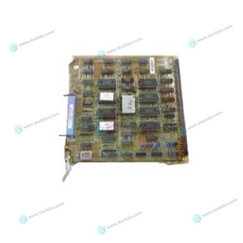
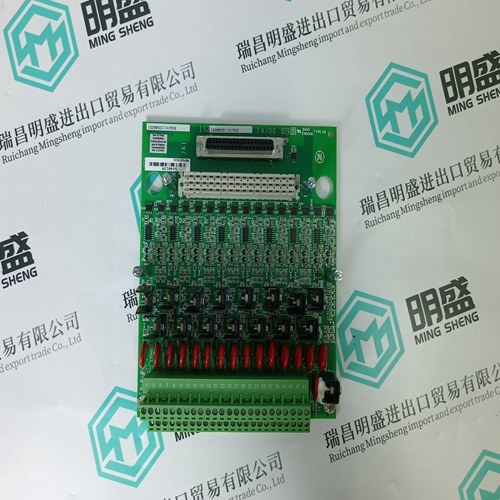
GE DS3815PRDB1H1A Gas turbine input module
- Product ID: DS3815PRDB1H1A
- Brand: GE
- Place of origin: The United States
- Goods status: new/used
- Delivery date: stock
- The quality assurance period: 365 days
- Phone/WhatsApp/WeChat:+86 15270269218
- Email:stodcdcs@gmail.com
- Tags:GEDS3815PRDB1H1AGas turbine input module
- Get the latest price:Click to consult
GE DS3815PRDB1H1A Gas turbine input module
• Do not enter the robot cell while it is in automatic operation. Programmers must have the teach pendant when they enter the robot cell. • Improper connections can damage the robot. All connections must be made within the standard voltage and current ratings of the robot I/O (Inputs and Outputs). • The robot must be placed in Emergency Stop (E-STOP) mode whenever it is not in use. • In accordance with ANSI/RIA R15.06-1999, section 4.2.5, Sources of Energy, use lockout/tagout procedures during equipment maintenance. Refer also to Section 1910.147 (29CFR, Part 1910), Occupational Safety and Health Standards for General Industry (OSHA). 2.4 Mechanical options and accessories should be permitted to operate this robot system.
Mechanical Safety Devices
The safe operation of the robot, positioner, auxiliary equipment, and system is ultimately the user's responsibility. The conditions under which the equipment will be operated safely should be reviewed by the user. The user must be aware of the various national codes, ANSI/RIA R15.06-1999 safety standards, and other local codes that may pertain to the installation and use of industrial equipment. Additional safety measures for personnel and equipment may be required depending on system installation, operation, and/or location. The following safety equipment is provided as standard:
• Safety fences and barriers • Light curtains and/or safety mats
• Door interlocks
• Emergency stop palm buttons located on operator station, robot controller, and programming pendant Check all safety equipment frequently for proper operation. Repair or replace any non-functioning safety equipment immediately
Installation Safety
Safe installation is essential for protection of people and equipment. The following suggestions are intended to supplement, but not replace, existing federal, local, and state laws and regulations. Additional safety measures for personnel and equipment may be required depending on system installation, operation, and/or location. Installation tips are as follows:
• Be sure that only qualified personnel familiar with national codes, local codes, and ANSI/RIA R15.06-1999 safety standards are permitted to install the equipment.
• Identify the work envelope of each robot with floor markings, signs, and barriers.
• Position all controllers outside the robot work envelope.


[Main Products]
Main products: PLC and DCS system spare parts modules of world famous brands
①Allen-Bradley 1756、1746、1747、1771、1785
②Schneider 140 Series PLC module
③General electric GE IC693 IC697 IC698 Series PLC module
DS200 DS3800 DS215 IS200 IS215 IS220 Series gas turbine module
VMIVME Control module of series
④Bently:3500 series cards 3500/22M、3500/15、3500/92 And other products
⑤ICS TRIPLEX
⑥ABB Robots. FANUC Robots、YASKAWA Robots、KUKA Robots、Mitsubishi Robots、OTC Robots、Panasonic Robots、MOTOMAN Robots。
⑦EMERSON:Spare parts for OVATION system, WDPF system and MAX1000 system.
⑧ Invensys Foxboro: I/A Series system, FBM (field input/output module) sequential control, ladder logic control, accident recall processing, digital analog conversion, input/output signal processing, data communication and processing, etc. Invensys Triconex: redundant fault-tolerant control system, Zui modern fault-tolerant controller based on triple module redundancy (TMR) structure.
⑨Woodward:505 series governor 9907-164 And other products
⑩Bosch Rexroth:Indramat,I/O module,PLC CPU,Motors, drives and other products.
◆Motorola:MVME 162、MVME 167、MVME1772、MVME177and other products.
