Home > Product > Gas turbine system > GE VMIVME-2170A Gas turbine output module
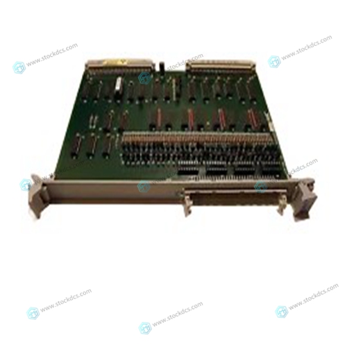
GE VMIVME-2170A Gas turbine output module
- Product ID: VMIVME-2170A
- Brand: GE
- Place of origin: The United States
- Goods status: new/used
- Delivery date: stock
- The quality assurance period: 365 days
- Phone/WhatsApp/WeChat:+86 15270269218
- Email:xiamen2018@foxmail.com
- Tags:GEVMIVME-2170AGas turbine output module
- Get the latest price:Click to consult
GE VMIVME-2170A Gas turbine output module
User Coordinates File Up to 24 kinds of user coordinates can be registered. Each coordinate has a user coordinate No. and is called a user coordinate file.The user coordinate list display is shown.z indicates that the user coordinates is completed to set and { indicates that it is not completed. To check the position of the user coodinates select {DISPLAY} Æ {COORDINATE DATA}. The user coordinate display is shown.Select the desired user coordinate number for setting in the user coordinate list display. The user coordinate teaching display is shown.Select the robot for teaching user coordinates. (When the robot has already been selected or there is only one robot, this operation should not be performed.) Select “**” in the user coordinates setting display and select the robot in the displayed selection dialog. The robot is registered.
The selection dialog is displayed. Select the teaching point
Taught position is registered. Repeat *2~*3 operation to teach ORG, XX and XY. z indicates that teaching is completed and { indicates that it is not completed.To check the taught positions, call up the required display among ORG to XY and press [FWD]. The manipulator moves to the set position. If there is a difference between the current position of the manipulator and the displayed position data, “ORG”, “XX”,or “XY” flashes. *4 User coordinates are registered in the file. Once the user coordinate setting is completed, the user coordinate list display is shown.
ARM Control
In XRC, the operation performance of the robot which satisfies various demands on the production site such as the improvement of the path accuracy and the cycle time shortening is achieved by adopting the ARM(Advanced Robot Motion) control which Yaskawa Electric Co., Ltd. originally developed. The moment of inertia and the gravity moment etc. of each axis are calculated in the ARM control, and XRC controls robot motion according to it. It is necessary to set the Robot setup condition and the tool load information to request these accurately. The robot setup condition is robot installation angle relative to ground and the weight and a center of gravity position of the load installed at each part of robot, etc. The tool load information is weight, a center of gravity position, and moment of inertia at the center of gravity, of the tool installed at the flange. It is necessary to set these information correctly to do a better operation control by the ARM control.


[Main Products]
Main products: PLC and DCS system spare parts modules of world famous brands
①Allen-Bradley 1756、1746、1747、1771、1785
②Schneider 140 Series PLC module
③General electric GE IC693 IC697 IC698 Series PLC module
DS200 DS3800 DS215 IS200 IS215 IS220 Series gas turbine module
VMIVME Control module of series
④Bently:3500 series cards 3500/22M、3500/15、3500/92 And other products
⑤ICS TRIPLEX
⑥ABB Robots. FANUC Robots、YASKAWA Robots、KUKA Robots、Mitsubishi Robots、OTC Robots、Panasonic Robots、MOTOMAN Robots。
⑦EMERSON:Spare parts for OVATION system, WDPF system and MAX1000 system.
⑧ Invensys Foxboro: I/A Series system, FBM (field input/output module) sequential control, ladder logic control, accident recall processing, digital analog conversion, input/output signal processing, data communication and processing, etc. Invensys Triconex: redundant fault-tolerant control system, Zui modern fault-tolerant controller based on triple module redundancy (TMR) structure.
⑨Woodward:505 series governor 9907-164 And other products
⑩Bosch Rexroth:Indramat,I/O module,PLC CPU,Motors, drives and other products.
◆Motorola:MVME 162、MVME 167、MVME1772、MVME177and other products.
