Home > Product > DCS control system > REF615C-D HCFFAEAGABC2BAA1XD control screen
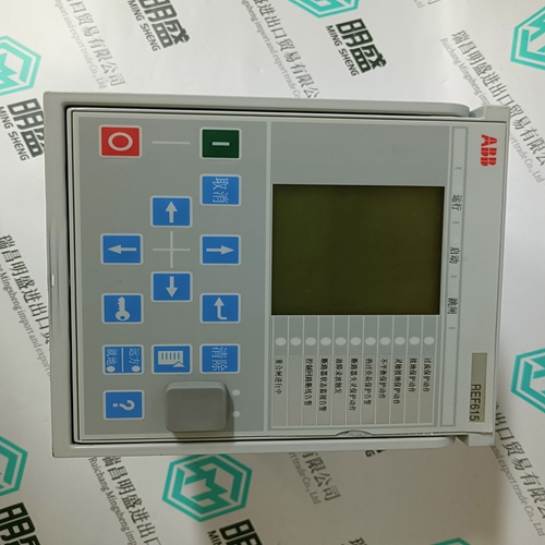
REF615C-D HCFFAEAGABC2BAA1XD control screen
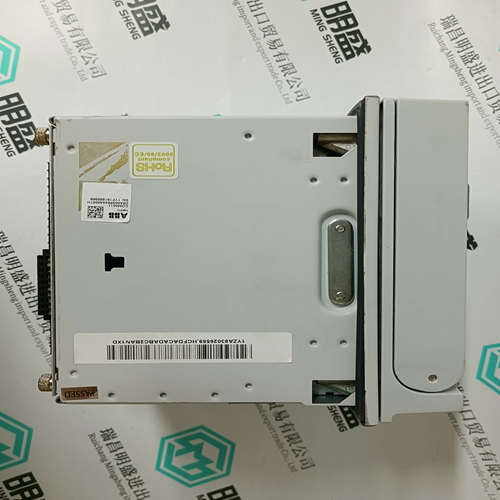
- Product ID: REF615C-D HCFFAEAGABC2BAA1XD
- Brand: ABB
- Place of origin: The Swiss
- Goods status: new/used
- Delivery date: stock
- The quality assurance period: 365 days
- Phone/WhatsApp/WeChat:+86 15270269218
- Email:stodcdcs@gmail.com
- Tags:REF615C-D HCFFAEAGABC2BAA1XDcontrol screen
- Get the latest price:Click to consult
The main products
Spare parts spare parts, the DCS control system of PLC system and the robot system spare parts,
Brand advantage: Allen Bradley, BentlyNevada, ABB, Emerson Ovation, Honeywell DCS, Rockwell ICS Triplex, FOXBORO, Schneider PLC, GE Fanuc, Motorola, HIMA, TRICONEX, Prosoft etc. Various kinds of imported industrial parts
REF615C-D HCFFAEAGABC2BAA1XD control screen
Each of the analog outputs can be assigned to two of the parameters listed in the Analog Output Parameters table. The analog output main selection is the default selection and a programmable switch input can be programmed to multiplex the ANALOG OUTPUT 1(4) ALT selection to the same output depending upon the open or closed state of the switch input. See 5.3.4 Switch Inputs for details about configuring a switch input. If no switch input is assigned as an analog output multiplexer, the analog output main selection will be the only parameter which appears at the analog output terminals. The ability to multiplex two different analog output quantities on one analog output effectively gives the PQMII eight analog outputs. The table below shows the criteria used by the PQMII to decide whether the output is based on MAIN or ALT settings. • MAIN/ALT 4 mA VALUE: This message appears for each analog output and allows the user to assign a numeric value which corresponds to the 4 mA end of the 4 to 20 mA signal range (T20 option) or the 0 mA end of the 0 to 1 mA signal range (T1 option). The numeric value range will depend upon which parameter is selected. See the Analog Output Parameters table below for details. Note that if the T20 option is installed and the ANALOG OUTPUT RANGE setpoint is set to “0-20 mA”, this message represents the 0 mA end of the signal range.
MAIN/ALT 20 mA VALUE
This message appears for each analog output and allows the user to assign a numeric value which corresponds to the 20 mA end of the 4 to 20 mA signal range (T20 option) or the 1 mA end of the 0 to 1 mA signal range (T1 option). The numeric value range will depend upon which parameter is selected. See the Analog Output Parameters table below. If the 4 mA (or 0 mA) value is programmed to be higher than the 20 mA (or 1 mA) value, the analog output will decrease towards 4 mA (or 0 mA) as the value increases and the analog output will increase towards 20 mA (or 1 mA) as the value decreases. If the 4 mA (or 0 mA) and 20 mA (or 1 mA) values are programmed to an identical value, the output will always be 4 mA (or 0 mA).
When the Analog Output parameter is set to “Serial Control”, the analog output(s) reflect a value in proportion to the serial value written to a specific register within the PQMII memory map. The locations are as described in the table below.