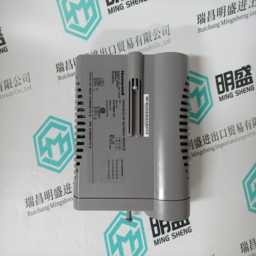
Home > Product > DCS control system > DI93a HESG440355R3 controller module
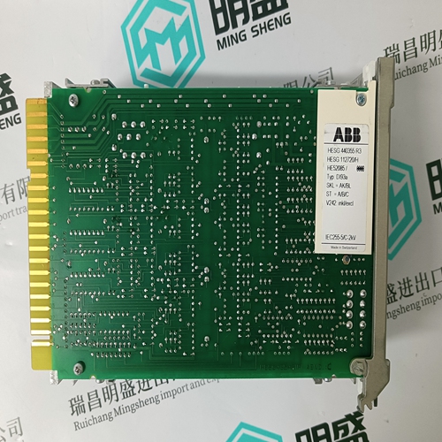
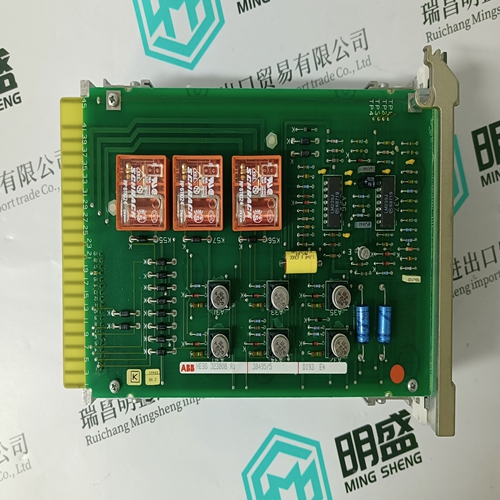
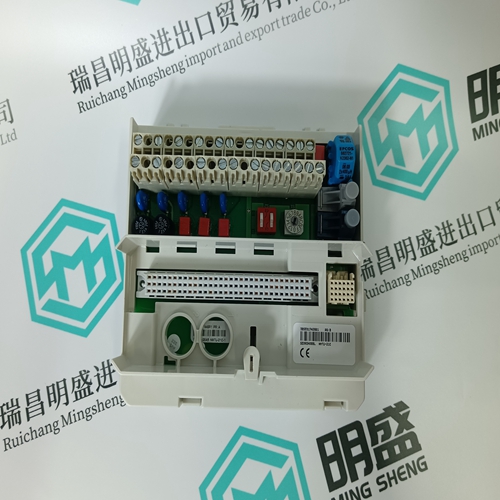
DI93a HESG440355R3 controller module
- Product ID: DI93a HESG440355R3
- Brand: ABB
- Place of origin: The Swiss
- Goods status: new/used
- Delivery date: stock
- The quality assurance period: 365 days
- Phone/WhatsApp/WeChat:+86 15270269218
- Email:stodcdcs@gmail.com
- Tags:DI93a HESG440355R3controller module
- Get the latest price:Click to consult
The main products
Spare parts spare parts, the DCS control system of PLC system and the robot system spare parts,
Brand advantage: Allen Bradley, BentlyNevada, ABB, Emerson Ovation, Honeywell DCS, Rockwell ICS Triplex, FOXBORO, Schneider PLC, GE Fanuc, Motorola, HIMA, TRICONEX, Prosoft etc. Various kinds of imported industrial parts
DI93a HESG440355R3 controller module
SAG LEVEL: When the voltage on any phase drops below this level a Sag condition occurs. During this condition, the average voltage and duration of the disturbance are calculated. The condition ends when the level increases to at least 10% of nominal plus pickup of the SAG LEVEL setting. This hysteresis is implemented to avoid nuisance alarms due to voltage fluctuations. If the duration logged was less then or equal to 1 minute an event with a sag type will be logged. If the duration was greater then 1 minute an event with an undervoltage type will be logged when this feature is configured. • SWELL LEVEL: When the voltage on any phase increases above this level a swell condition occurs. During a swell condition the average voltage and duration of the disturbance are calculated. To end a Swell condition the level must decrease to pickup minus 10% of nominal of the SWELL LEVEL setting. This hysteresis is implemented to avoid nuisance alarms due to voltage fluctuations. If the duration logged was less then or equal to 1 minute an event with a swell type will be logged. If the duration was greater then 1 minute an event with an overvoltage type will be logged when this feature is configured.
S3 Output Relays
Output relay operation in the PQMII occurs in either ‘failsafe’ or ‘non-failsafe’ modes, as defined below: • Non-failsafe: The relay coil is not energized in its non-active state. Loss of control power will cause the relay to remain in the non-active state. That is, a non-failsafe alarm relay will not cause an alarm on loss of control power. Contact configuration in the Wiring Diagrams is shown with relays programmed non-failsafe and control power not applied. • Failsafe: The relay coil is energized in its non-active state. Loss of control power will cause the relay to go into its active state. That is, a failsafe alarm relay will cause an alarm on loss of control power. Contact configuration is opposite to that shown in the Wiring Diagrams for relays programmed as failsafe when control power is applied. ALARM OPERATION: The terms ‘failsafe’ and ‘non-failsafe’ are defined above as implemented in the PQMII. If an alarm is required when the PQMII is not operational due to a loss of control power, select failsafe operation. Otherwise, choose nonfailsafe. • ALARM ACTIVATION: If an alarm indication is required only while an alarm is present, select unlatched. Once the alarm condition disappears, the alarm and associated message automatically clear. To ensure all alarms are acknowledged, select latched. Even if an alarm condition is no longer present, the alarm relay and message can only be cleared by pressing the key or by sending the reset command via the computer.
